77
Unit Components Section 2-2
8. Connector
Connects to CPU Unit communications port.
2-2-7 CPM2C-CIF01-V1 Peripheral/RS-232C Adapter Unit
1,2,3... 1. Peripheral Port
Used to connect to Programming Devices (including Programming Con-
soles), host computers, or general-purpose external devices. Use a spe-
cial connecting cable (CS1W-CN114, CS1W-CN118) for connections.
With the CPM2C-CIF01-V1, the cable switch (SW1) can be turned ON to
enable connecting to a personal computer with a CS1W-CN226/CN626
Connecting Cable.
Note a) The C200H-PRO27-E Programming Console can be connected
directly to the CPM2C’s CPU Unit using a special connecting ca-
ble (CS1W-CN224/624).
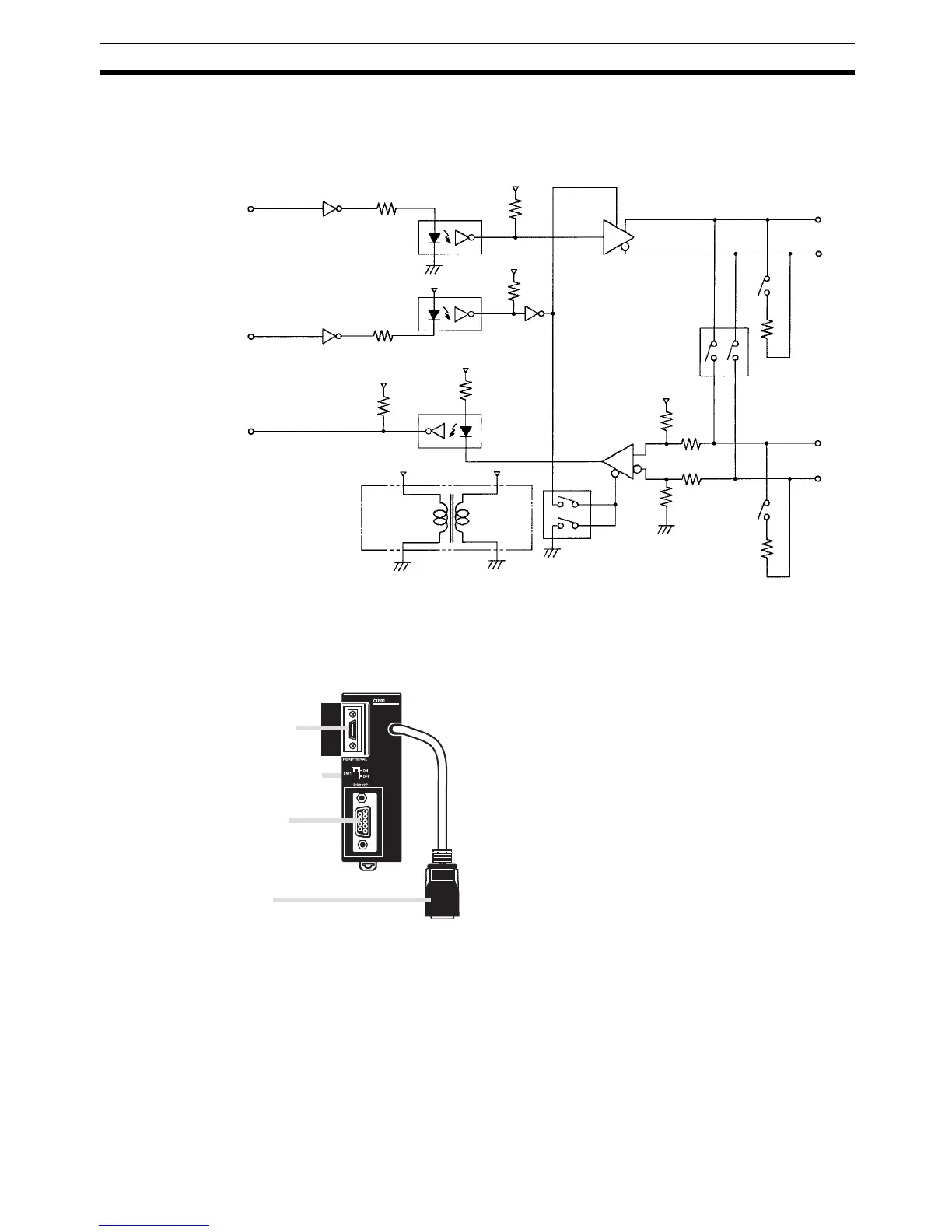
RS-422 Interface Block Diagram
TxD
SE
RxD
0 V
C5V
5 V
5 V
C5V
0 V
C0V
C0V
C0V
SW4
C5V
C5V
C5V
SDB
SDA
SW4
SW1
12
RDB
RDA
SW1
4
3
5 V
Front View
1. Peripheral port
3. RS-232C port
4. Connector
Do not use the CPM2C-CIF01-V1 with any PC other than the
CPM2C. Do not connect another CPM2C-CIF01-V1 or the
CPM2C-CIF11 to the CPM2C-CIF01-V1. The CPM2C-CN111 can
be connected to the CPM2C-CIF01, but the peripheral port and
the RS-232C port of the CPM2C-CN111 cannot be used
simultaneously. If an attempt to use these ports simultaneously is
made, communications will not be performed properly, and this
may result in malfunction of equipment.
*: The CPM2C-CIF01 does not have a cable switch (SW1).
2. Cable switch (SW1)