101
Wiring and Connections Section 3-4
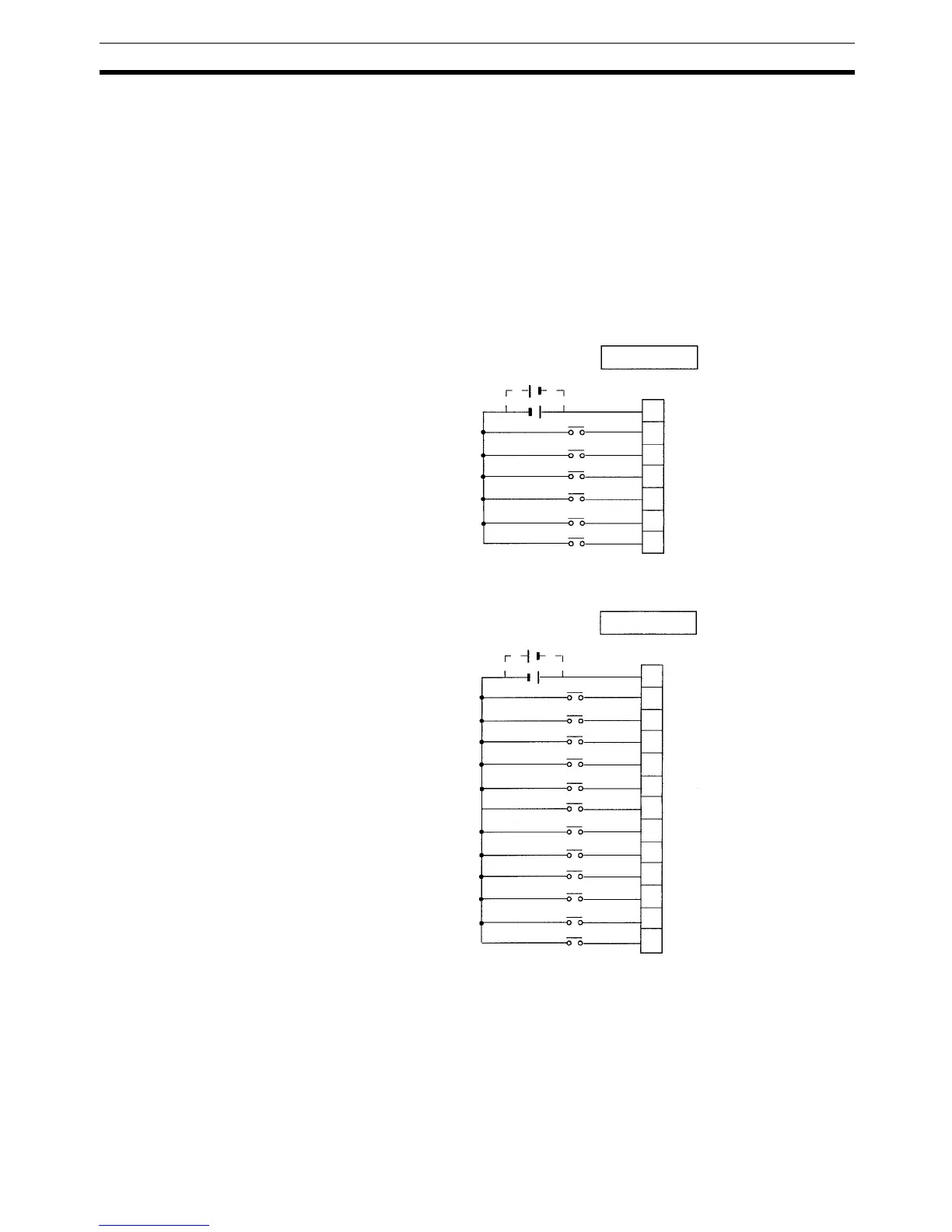
3-4-7 Connecting Input Devices
Wire inputs to the CPM2C’s CPU Unit and Expansion I/O Units as shown in
the following diagrams.
Note 1. Be sure to make connections to terminal blocks and connectors with the
correct direction and polarity. Output transistor fuses may burn out if power
is supplied to I/O circuits with the I/O connector connected in reverse.
2. When equipment must conform to the EC Directives (Low-voltage Direc-
tives), use a power supply with double insulation or reinforced insulation.
Units with Relay Outputs
via Terminal Block
The following diagrams show the input configurations.
CPU Units with 10 I/O Points: CPM2C-10C@DR-D
CPU Units with 20 I/O Points: CPM2C-20C@DR-D
In