116
Wiring and Connections Section 3-4
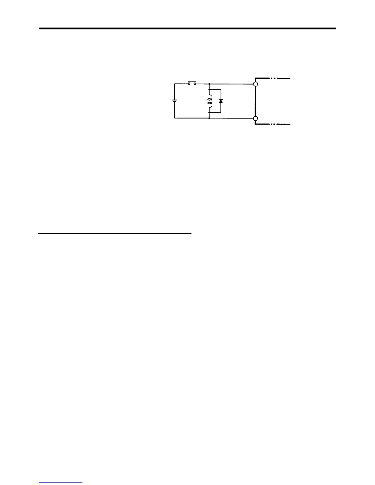
Inductive Loads When connecting an inductive load to an input, connect a diode in parallel
with the load. The diode should satisfy the following requirements:
1,2,3... 1. Peak reverse-breakdown voltage must be at least 3 times the load voltage.
2. Average rectified current must be 1 A.
3-4-8 Connecting Output Devices
Wire the outputs to the CPM2C’s CPU Unit and Expansion I/O Unit as shown
in the following diagrams.
Don’t exceed the output capacity or the maximum common current shown in
the following table.
!WARNING The PC outputs may remain ON or OFF due to deposits on or burning of the
output relays or destruction of the output transistors. External safety mea-
sures must be provided to ensure safety in the system. Not providing proper
safety measures may result in serious accidents.
Units with Relay Outputs via Terminal Block
Note 1. Be sure to make connections to terminal blocks and connectors with the
correct direction and polarity. Output transistor fuses may burn out if power
is supplied to I/O circuits with the I/O connector connected in reverse.
2. Basic insulation is provided between the commons of different polarities of
the output relay for the CPM2C-20@@R (model with 20 relay output
points).
Therefore, to conform to EC Directives (Low Voltage Directive), when con-
necting devices that operate at voltages higher than 50 VAC and those that
operate on DC power supplies to adjoining relay output terminals, use dif-
ferent DC power supplies for output devices from those for input devices
and the CPM2C power supply.
3. If input status is being held in HR area bits or counter values are being held
when the power supply turns OFF, configure the system so that the I/O
power supply turns OFF after the power supply to the CPM2C or delay
reading the status of inputs.
IN
COM
CPM2C
Diode