93
Wiring and Connections Section 3-4
3-4-4 Removing and Wiring I/O Terminal Blocks
The following tables provide I/O terminal block specifications.
Terminal Block
Specifications
Recommended Wire and
Terminals
Note 1. When using stranded wire, be sure to avoid stray wire strands that might
short-circuit an adjacent terminal.
2. Do not solder the ends of stranded wires. Solder can break and cause wir-
ing problems. Also, the solder can cause corrosion on the contact surface.
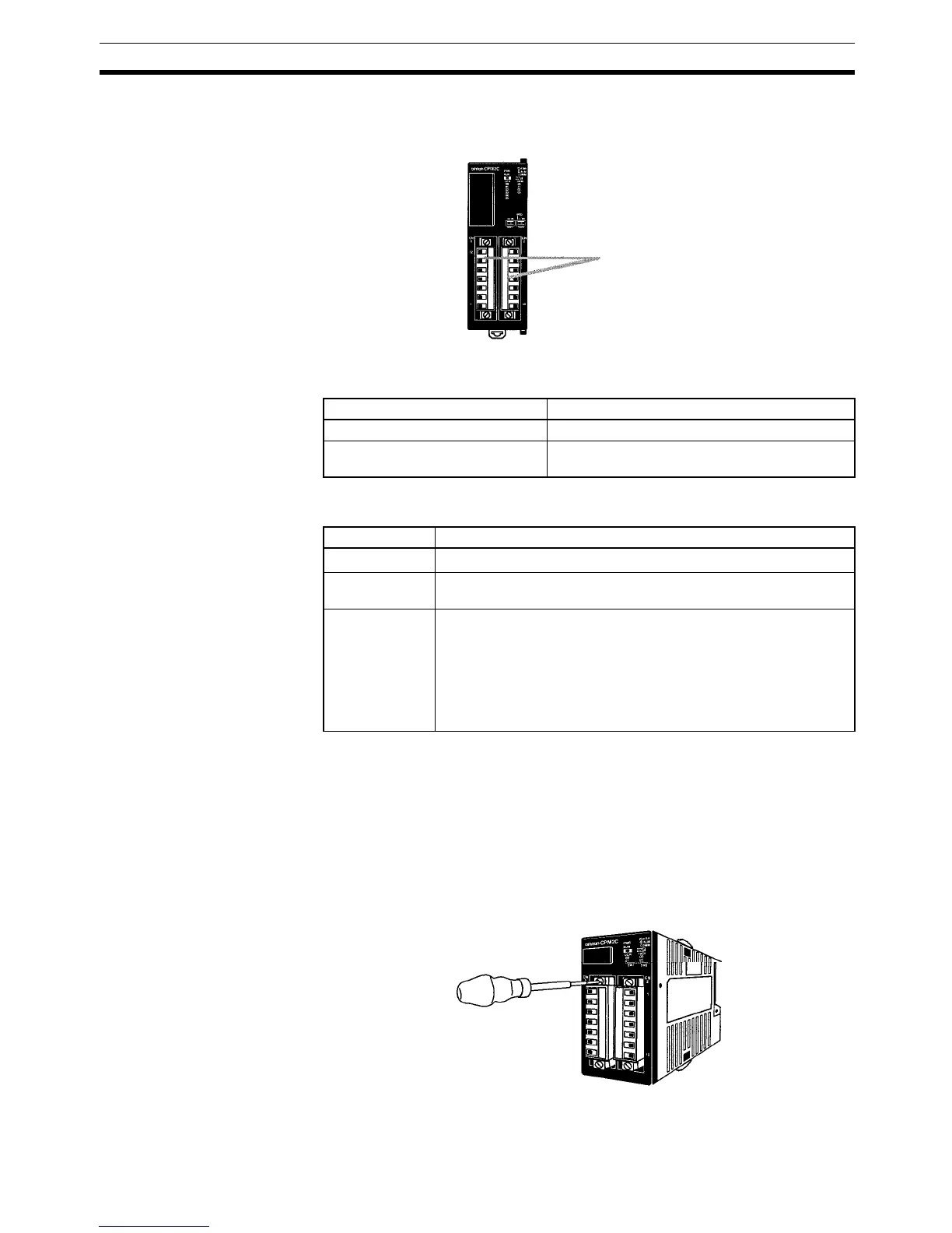
Removing and Wiring a
Terminal Block
Use the following procedure when wiring a terminal block.
1,2,3... 1. Loosen the screws at the top and bottom of the terminal block as shown in
the following diagram.
I/O terminal blocks
Item Specification
Screw size M2
Recommended tightening torque 0.22 to 0.25 N·m
Recommended Screwdriver: XW4Z-00B
Item Specification
Solid wire
0.14 to 1.5 mm
2
(AWG 28 to AWG 16) (Strip 7 mm.)
Stranded wire
(See notes.)
0.14 to 1.5 mm
2
(AWG 28 to AWG 16) (Strip 7 mm.)
Pin terminal
0.25 to 1.5 mm
2
, 7-mm terminal length
Recommended pin terminals
Phoenix AI0.25-8Y; Applicable wire size: 0.2 to 0.25 mm
2
Phoenix AI0.34-8TQ; Applicable wire size: 0.25 to 0.34 mm
2
Phoenix AI0.5-8WH; Applicable wire size: 0.34 to 0.50 mm
2
Phoenix AI-TWIN2×0.5-8WH; Applicable wire size: 2×0.50 mm
2