149
Wiring and Connections Section 3-4
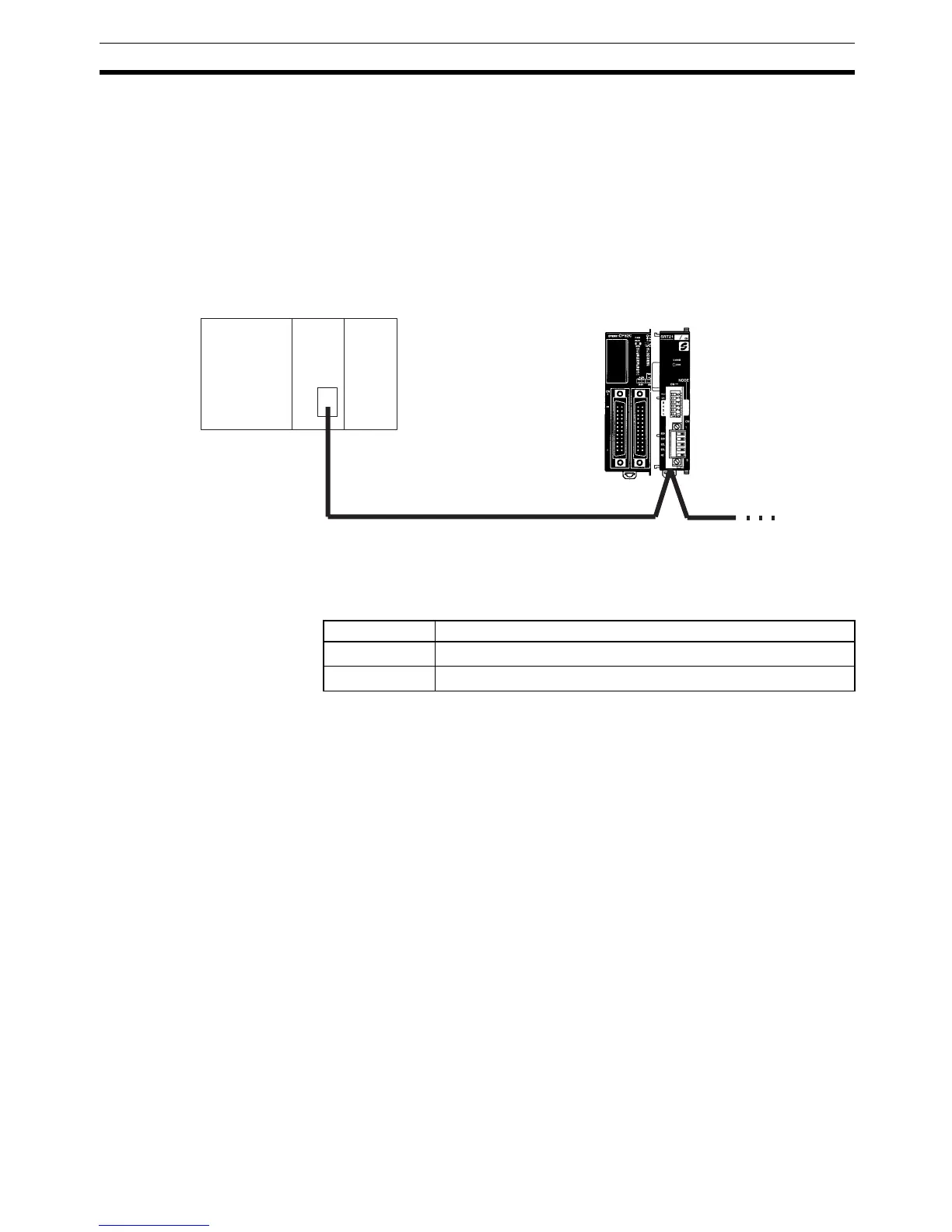
3-4-14 CompoBus/S I/O Link Connections
A CompoBus/S I/O Link can be used to create an I/O link (remote I/O) of 8
input points and 8 output points with a CompoBus/S Master Unit or SRM1 PC.
The connection is made through a CompoBus/S I/O Link Unit.
From the standpoint of the CPM2C CPU Unit, the area allocated to the Com-
poBus/S I/O Link Unit can be treated just like the area allocated to an Expan-
sion I/O Unit. The difference is that the bits are not actual I/O points, but I/O
bits in the Master Unit.
Cables
Use special flat cable or VCTF cable to connect the nodes in the CompoBus/
S I/O Link. (Special flat cables and VCTF cables cannot be combined in the
same system.)
CPM2C CPU Unit
CompoBus/S Master Unit (or SRM1 PC)
C200HX/HG/HE PC
CompoBus/S I/O Link Unit
(Slave)
Name Specifications
Flat cable
4-core flat cable, 0.75 mm
2
VCTF cable
2-core x 0.75 mm
2