233
Preparation for Operation Section 7-3
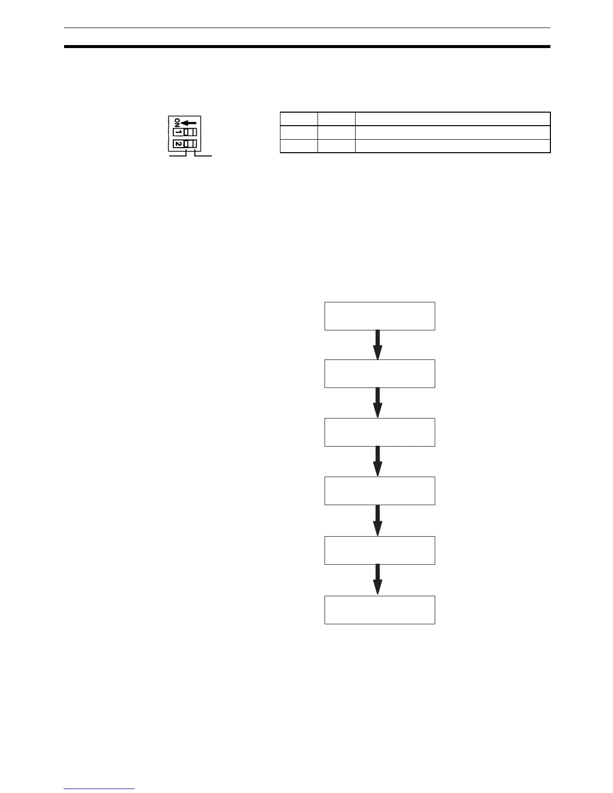
Turn ON both SW4-1 and SW4-2 if the Simple Communications Unit is at
the end of the RS-422/RS-485 transmission path. Remove the cover on
the top of the Unit to access SW4. If the cover is difficult to remove, use a
flat-blade screwdriver or similar tool.
Note a) Both pins are set to OFF at the factory.
b) Terminating Resistance
RS-422: 235
Ω (combined resistance must be 110 Ω min)
RS-485: 118
Ω (combined resistance must be 54 Ω min)
7-3 Preparation for Operation
This section describes the procedures to prepare for communications.
7-3-1 Unit Connections
Connect the Simple Communications Unit to the PC’s CPU Unit. Power is
supplied from the CPU Unit to the Simple Communications Unit through the
communications cable.
Connect components through their RS-422 or RS-485 interfaces. Up to 32
components can be connected.
SW4-1 SW4-2 Function
ON ON Terminating resistance connected.
OFF OFF Terminating resistance disconnected.
Resistance
not connected
SW4
Resistance
connected
Unit connections
Switch settings
PC settings
Component settings
DM settings
Communications
with components