EasyManua.ls Logo

Omron CPM2C User Manual

Omron CPM2C
325 pages
To Next Page IconTo Next Page
To Previous Page IconTo Previous Page
Page #195 background imageLoading...
Page #195 background image
172
Programming Console Operations Section 4-2
If errors are displayed, edit the program to correct the errors and check the
program again. Continue checking the program by pressing the SRCH Key
again until all errors have been corrected.
4-2-14 Bit, Digit, Word Monitor
This operation is used to monitor the status of up to 16 bits and words,
although only 3 can be shown on the display at any one time. Operation is
possible in any mode.
Program Read then
Monitor
When a program address is being displayed, the status of the bit or word in
that address can be monitored by pressing the MONTR Key.
1,2,3... 1. Press the CLR Key to bring up the initial display.
2. Input the desired program address and press the Down Arrow Key.
3. Press the MONTR Key to begin monitoring.
If the status of a bit is being monitored, that bit’s status can be changed
using the Force Set/Reset operation. Refer to
4-2-26 Force Set, Reset for
details.
If the status of a word is being monitored, that word’s value can be changed
using the Hexadecimal/BCD Data Modification operation. Refer to
4-2-22
Hexadecimal, BCD Data Modification
, 4-2-23 Binary Data Modification, 4-
2-24 Signed Decimal Data Modification
, and 4-2-25 Unsigned Decimal
Data Modification
for details.
4. Press the CLR Key to end monitoring.
Bit Monitor Follow the procedure below to monitor the status of a particular bit.
1,2,3... 1. Press the CLR Key to bring up the initial display.
2. Input the bit address of the desired bit and press the MONTR Key.
The Up or Down Arrow Key can be pressed to display the status of the pre-
vious or next bit.
The displayed bit’s status can be changed using the Force Set/Reset op-
eration in MONITOR or PROGRAM mode. Refer to
4-2-26 Force Set, Re-
set
for details.
3. Press the CLR Key to end monitoring.
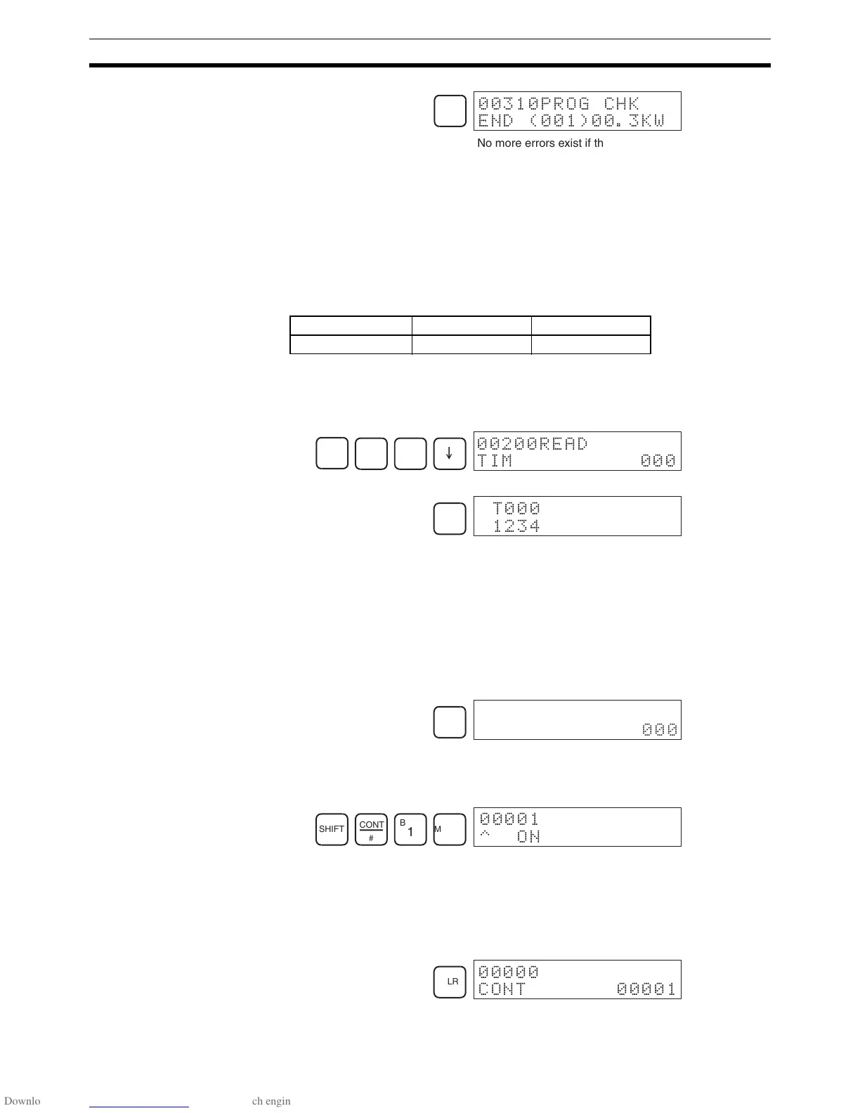
SRCH
00310PROG CHK
END (001)00.3KW
No more errors exist if the END
instruction is displayed.
RUN MONITOR PROGRAM
OK OK OK
C
2
A
0
A
0
E
00200READ
TIM 000
MONTR
6
!"
CLR
00200
TIM 000
SHIFT
CONT
#
B
1
MONTR
00001
^ON
CLR
00000
CONT 00001

Table of Contents

Question and Answer IconNeed help?

Do you have a question about the Omron CPM2C and is the answer not in the manual?

Omron CPM2C Specifications

General IconGeneral
TypeProgrammable Logic Controller (PLC)
Input Voltage24 VDC
Number of OutputsUp to 16
Communication PortsRS-232C
Programming LanguageLadder Logic
MountingDIN rail
CPUBuilt-in
Timer/Counter256 timers/counters
Analog InputOptional
Analog OutputOptional
Storage Temperature-25°C to 70°C
Memory4K words
Program Memory4K words
Humidity25 to 85% RH (non-condensing)

Summary

PRECAUTIONS

Safety Precautions

Critical safety warnings regarding grounding, live components, and external circuit safety measures.

Application Precautions

Crucial safety guidelines for system applications, emphasizing risk assessment and proper product use.

Operating Environment Precautions

Lists unsuitable locations and requirements for shielding against noise and environmental factors.

SECTION 1 Introduction

1-1 CPM2C Features and Functions

Introduces the CPM2C's special features, functions, system configurations, and capabilities.

1-2 System Configurations

Details possible system configurations, including CPU units, expansion units, and I/O units.

1-3 Structure and Operation

Explains CPU Unit internal structure, operating modes, and startup behavior.

1-6 Preparation for Operation

Outlines essential steps for initial system setup and Programming Console operation.

SECTION 2 Unit Components and Specifications

2-1 Specifications

Provides detailed technical specifications, including general, I/O, and power supply unit specs.

2-2 Unit Components

Describes physical components of CPU units, expansion I/O units, and various adapter units.

SECTION 3 Installation and Wiring

3-1 Design Precautions

Essential design considerations for power supply wiring, voltage, and safety circuits like interlocks.

3-3 Installing the CPM2C

Covers the procedure for installing the CPM2C unit and connecting expansion units.

3-4 Wiring and Connections

Provides fundamental information on wiring power supply, I/O terminals, connectors, and communication devices.

SECTION 4 Using a Programming Console

4-1 Using a Programming Console

Information on connecting and operating the Programming Console, including compatible models and mode switching.

4-2 Programming Console Operations

Details various operations like clearing memory, editing programs, searching, and monitoring functions.

4-3 Programming Example

Demonstrates writing a program using the console, including preparatory steps and a test run.

SECTION 5 Test Runs and Error Processing

5-1 Initial System Checks and Test Run Procedure

Outlines initial system checks, test runs, and flash memory precautions.

5-2 Self-diagnostic Functions

Explains error identification via messages, flags, and codes for accurate troubleshooting.

5-5 Troubleshooting Flowcharts

Provides visual flowcharts for diagnosing and resolving operational errors like power supply or I/O issues.

5-7 Battery Replacement

Details the procedure for replacing the backup battery with necessary safety warnings.

SECTION 6 Expansion Memory Unit

6-1 Overview

Introduces the Expansion Memory Unit, its memory areas, and general precautions for use.

6-2 Specifications and Nomenclature

Lists specifications and identifies components of the Expansion Memory Unit, including supported PCs and connectors.

6-3 Handling

Covers unit handling, including EEPROM mounting, PC connections, and program upload/download procedures.

SECTION 7 Simple Communications Unit

7-1 Introduction

Introduces the unit's features, system configuration, and component data processing methods.

7-3 Preparation for Operation

Details procedures for unit connections, switch settings, PC setup, and component configuration.

7-7 Error Processing

Explains detection and processing of fatal and non-fatal errors specific to the Simple Communications Unit.

7-9 Example Application

Demonstrates system configuration and DM settings for using the unit with temperature controllers.

Related product manuals