EasyManua.ls Logo

Omron CPM2C User Manual

Omron CPM2C
325 pages
To Next Page IconTo Next Page
To Previous Page IconTo Previous Page
Page #184 background imageLoading...
Page #184 background image
161
Programming Console Operations Section 4-2
4-2-2 Clearing Memory
This operation is used to clear all or part of the Program Memory and data
areas, as well as the contents of the Programming Console’s memory. This
operation is possible in PROGRAM mode only.
Before beginning to program for the first time or when installing a new pro-
gram, clear all areas.
All Clear The following procedure is used to clear memory completely, including the
program, all data areas, counter PVs, Data Memory, and the PC Setup (DM
6600 to DM 6655).
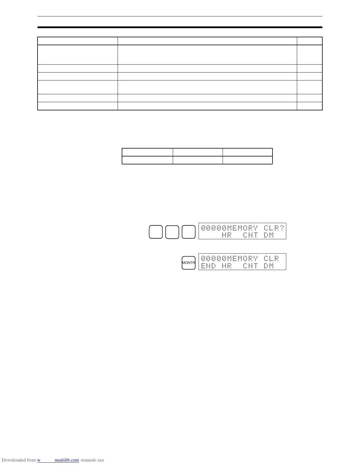
1,2,3... 1. Bring up the initial display by pressing the CLR Key repeatedly.
2. Press the SET, NOT, and then the RESET Key to begin the operation.
3. Press the MONTR Key to clear memory completely.
!Caution The PC Setup (DM 6600 through DM 6655) will be cleared when this opera-
tion is performed.
Partial Clear It is possible to retain the data in specified areas or part of the Program Mem-
ory. To retain the data in the HR, TC, or DM Areas, press the appropriate key
after pressing SET, NOT, and RESET. Any data area that still appears on the
display will be cleared when the MONTR Key is pressed.
The HR Key is used to specify both the AR and HR Areas, the CNT Key is
used to specify the entire timer/counter area, and the DM Key is used to spec-
ify the DM Area.
It is also possible to retain a portion of the Program Memory from the first
memory address to a specified address. After designating the data areas to
be retained, specify the first Program Memory address to be cleared. For
example, input 030 to leave addresses 000 to 029 untouched, but to clear
addresses from 030 to the end of Program Memory.
As an example, follow the procedure below to retain the timer/counter area
and Program Memory addresses 000 through 122:
1,2,3... 1. Press the CLR Key to bring up the initial display.
2. Press the SET, NOT, and then the RESET Key to begin the operation.
3. Press the CNT Key to remove the timer/counter area from the data areas
shown on the display. (Counter PVs will not be cleared.)
Unsigned decimal data modifi-
cation
Changes the decimal value of a word being monitored as unsigned decimal
data, within a range of 0 to 65,535. A change into hexadecimal data is made
automatically.
181
Force set/reset Forces bits ON (force set) or OFF (force reset.) 181
Clear force set/reset Restores the status of all bits which have been force set of reset. 182
Hex-ASCII display change Converts word data displays back and forth between 4-digit hexadecimal
data and ASCII.
183
Displaying the cycle time Displays the current average cycle time (scan time.) 183
Reading and setting the clock Reads or sets the internal clock. 184
Name Function Page
RUN MONITOR PROGRAM
No No OK
SET
NOT
RESET
00000MEMORY CLR?
HR CNT DM
MONTR
00000MEMORY CLR
END HR CNT DM

Table of Contents

Question and Answer IconNeed help?

Do you have a question about the Omron CPM2C and is the answer not in the manual?

Omron CPM2C Specifications

General IconGeneral
TypeProgrammable Logic Controller (PLC)
Input Voltage24 VDC
Number of OutputsUp to 16
Communication PortsRS-232C
Programming LanguageLadder Logic
MountingDIN rail
CPUBuilt-in
Timer/Counter256 timers/counters
Analog InputOptional
Analog OutputOptional
Storage Temperature-25°C to 70°C
Memory4K words
Program Memory4K words
Humidity25 to 85% RH (non-condensing)

Summary

PRECAUTIONS

Safety Precautions

Critical safety warnings regarding grounding, live components, and external circuit safety measures.

Application Precautions

Crucial safety guidelines for system applications, emphasizing risk assessment and proper product use.

Operating Environment Precautions

Lists unsuitable locations and requirements for shielding against noise and environmental factors.

SECTION 1 Introduction

1-1 CPM2C Features and Functions

Introduces the CPM2C's special features, functions, system configurations, and capabilities.

1-2 System Configurations

Details possible system configurations, including CPU units, expansion units, and I/O units.

1-3 Structure and Operation

Explains CPU Unit internal structure, operating modes, and startup behavior.

1-6 Preparation for Operation

Outlines essential steps for initial system setup and Programming Console operation.

SECTION 2 Unit Components and Specifications

2-1 Specifications

Provides detailed technical specifications, including general, I/O, and power supply unit specs.

2-2 Unit Components

Describes physical components of CPU units, expansion I/O units, and various adapter units.

SECTION 3 Installation and Wiring

3-1 Design Precautions

Essential design considerations for power supply wiring, voltage, and safety circuits like interlocks.

3-3 Installing the CPM2C

Covers the procedure for installing the CPM2C unit and connecting expansion units.

3-4 Wiring and Connections

Provides fundamental information on wiring power supply, I/O terminals, connectors, and communication devices.

SECTION 4 Using a Programming Console

4-1 Using a Programming Console

Information on connecting and operating the Programming Console, including compatible models and mode switching.

4-2 Programming Console Operations

Details various operations like clearing memory, editing programs, searching, and monitoring functions.

4-3 Programming Example

Demonstrates writing a program using the console, including preparatory steps and a test run.

SECTION 5 Test Runs and Error Processing

5-1 Initial System Checks and Test Run Procedure

Outlines initial system checks, test runs, and flash memory precautions.

5-2 Self-diagnostic Functions

Explains error identification via messages, flags, and codes for accurate troubleshooting.

5-5 Troubleshooting Flowcharts

Provides visual flowcharts for diagnosing and resolving operational errors like power supply or I/O issues.

5-7 Battery Replacement

Details the procedure for replacing the backup battery with necessary safety warnings.

SECTION 6 Expansion Memory Unit

6-1 Overview

Introduces the Expansion Memory Unit, its memory areas, and general precautions for use.

6-2 Specifications and Nomenclature

Lists specifications and identifies components of the Expansion Memory Unit, including supported PCs and connectors.

6-3 Handling

Covers unit handling, including EEPROM mounting, PC connections, and program upload/download procedures.

SECTION 7 Simple Communications Unit

7-1 Introduction

Introduces the unit's features, system configuration, and component data processing methods.

7-3 Preparation for Operation

Details procedures for unit connections, switch settings, PC setup, and component configuration.

7-7 Error Processing

Explains detection and processing of fatal and non-fatal errors specific to the Simple Communications Unit.

7-9 Example Application

Demonstrates system configuration and DM settings for using the unit with temperature controllers.

Related product manuals