EasyManua.ls Logo

Omron CPM2C User Manual

Omron CPM2C
325 pages
To Next Page IconTo Next Page
To Previous Page IconTo Previous Page
Page #221 background imageLoading...
Page #221 background image
198
Programming Console Operation Errors Section 5-3
5-2-5 Communications Errors
The COMM indicator will be turned OFF and AR 0812 will be turned ON if an
error occurs in communications through the peripheral port or AR 0804 will be
turned ON if an error occurs in communications through the RS-232C port.
Check the connecting cables and restart.
There are no error messages or error codes generated by this error and the
ERR/ALM indicator is not affected.
5-3 Programming Console Operation Errors
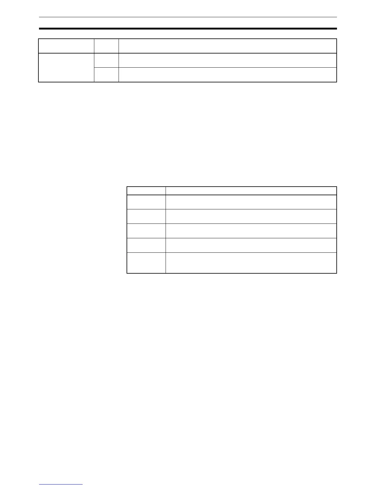
The following error messages may appear when performing operations on the
Programming Console. Correct the error as indicated and continue operation.
Note Refer to the relevant Support Software Operation Manual for details on errors
that may appear when operating the SSS or SYSMAC-CPT Support Soft-
ware.
5-4 Programming Errors
These errors in program syntax will be detected when the program is checked
using the Program Check operation.
Three levels of program checking are available. The desired level must be
designated to indicate the type of errors that are to be detected. The following
table provides the error types, displays, and explanations of all syntax errors.
SYS FAIL FALS**
(** is 01 to 99 or 9F.)
01 to 99 A FALS(07) instruction has been executed in the program. Check the FALS number to
determine the conditions that caused execution, correct the cause, and clear the error.
9F The cycle time has exceeded the Maximum (Watch) Cycle Time setting (DM 6618).
Check the cycle time and adjust the Maximum Cycle Time setting if necessary.
Message FALS
No.
Meaning and appropriate response
Message Meaning and appropriate response
REPL ROM An attempt was made to write to write-protected memory. Set bits 00
to 03 of DM 6602 to “0.
PROG OVER The instruction at the last address in memory is not NOP(00). Erase
all unnecessary instructions after END(01).
ADDR OVER An address was set that is larger than the highest memory address
in Program Memory. Input a smaller address.
SETDATA
ERR
FALS 00 has been input, and “00” cannot be input. Reinput the data.
I/O NO. ERR A data area address has been designated that exceeds the limit of
the data area, e.g., an address is too large. Confirm the requirements
for the instruction and re-enter the address.

Table of Contents

Question and Answer IconNeed help?

Do you have a question about the Omron CPM2C and is the answer not in the manual?

Omron CPM2C Specifications

General IconGeneral
TypeProgrammable Logic Controller (PLC)
Input Voltage24 VDC
Number of OutputsUp to 16
Communication PortsRS-232C
Programming LanguageLadder Logic
MountingDIN rail
CPUBuilt-in
Timer/Counter256 timers/counters
Analog InputOptional
Analog OutputOptional
Storage Temperature-25°C to 70°C
Memory4K words
Program Memory4K words
Humidity25 to 85% RH (non-condensing)

Summary

PRECAUTIONS

Safety Precautions

Critical safety warnings regarding grounding, live components, and external circuit safety measures.

Application Precautions

Crucial safety guidelines for system applications, emphasizing risk assessment and proper product use.

Operating Environment Precautions

Lists unsuitable locations and requirements for shielding against noise and environmental factors.

SECTION 1 Introduction

1-1 CPM2C Features and Functions

Introduces the CPM2C's special features, functions, system configurations, and capabilities.

1-2 System Configurations

Details possible system configurations, including CPU units, expansion units, and I/O units.

1-3 Structure and Operation

Explains CPU Unit internal structure, operating modes, and startup behavior.

1-6 Preparation for Operation

Outlines essential steps for initial system setup and Programming Console operation.

SECTION 2 Unit Components and Specifications

2-1 Specifications

Provides detailed technical specifications, including general, I/O, and power supply unit specs.

2-2 Unit Components

Describes physical components of CPU units, expansion I/O units, and various adapter units.

SECTION 3 Installation and Wiring

3-1 Design Precautions

Essential design considerations for power supply wiring, voltage, and safety circuits like interlocks.

3-3 Installing the CPM2C

Covers the procedure for installing the CPM2C unit and connecting expansion units.

3-4 Wiring and Connections

Provides fundamental information on wiring power supply, I/O terminals, connectors, and communication devices.

SECTION 4 Using a Programming Console

4-1 Using a Programming Console

Information on connecting and operating the Programming Console, including compatible models and mode switching.

4-2 Programming Console Operations

Details various operations like clearing memory, editing programs, searching, and monitoring functions.

4-3 Programming Example

Demonstrates writing a program using the console, including preparatory steps and a test run.

SECTION 5 Test Runs and Error Processing

5-1 Initial System Checks and Test Run Procedure

Outlines initial system checks, test runs, and flash memory precautions.

5-2 Self-diagnostic Functions

Explains error identification via messages, flags, and codes for accurate troubleshooting.

5-5 Troubleshooting Flowcharts

Provides visual flowcharts for diagnosing and resolving operational errors like power supply or I/O issues.

5-7 Battery Replacement

Details the procedure for replacing the backup battery with necessary safety warnings.

SECTION 6 Expansion Memory Unit

6-1 Overview

Introduces the Expansion Memory Unit, its memory areas, and general precautions for use.

6-2 Specifications and Nomenclature

Lists specifications and identifies components of the Expansion Memory Unit, including supported PCs and connectors.

6-3 Handling

Covers unit handling, including EEPROM mounting, PC connections, and program upload/download procedures.

SECTION 7 Simple Communications Unit

7-1 Introduction

Introduces the unit's features, system configuration, and component data processing methods.

7-3 Preparation for Operation

Details procedures for unit connections, switch settings, PC setup, and component configuration.

7-7 Error Processing

Explains detection and processing of fatal and non-fatal errors specific to the Simple Communications Unit.

7-9 Example Application

Demonstrates system configuration and DM settings for using the unit with temperature controllers.

Related product manuals