254
DM Settings and Component Communications Section 7-5
• Comparison value (L): The SV won’t be written.
• Comparison value (LL): The SV won’t be written.
Note The decimal point position has to be managed by the user since the Digital
Panel Meter’s decimal point position is not transferred in SYSWAY (X format)
communications.
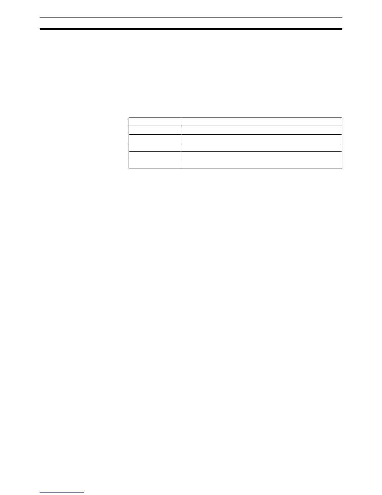
Operation Command (Offset: +2)
Store the operation command code (0000 to 0004) in this word. When a com-
mand group that includes the operation command is selected, the corre-
sponding operation command will be sent to the Temperature controller.
Note 1. When selecting the RAM write mode or backup mode, program the selec-
tion operation so that it is executed only one scan. Some components write
to EEPROM when this selection is made, and if it is made each scan, the
service live of the EEPROM will be affected.
2. There are restrictions on the number of times data can be written to the
Temperature Controller’s non-volatile memory. When frequently sending
data to a Temperature Controller, either set the Write Command Bit to 0 af-
ter writing is completed, or set the write mode for the Temperature Control-
ler to RAM write mode. Also, execute commands to select the RAM write
mode and backup mode in only one scan. Some devices will write to non-
volatile memory each time the modes are selected, and the life of the non-
volatile memory will be exhausted much more quickly if selections are
made every scan.
7-5 DM Settings and Component Communications
This section explains the basic procedures required to communicate with con-
nected components. Refer to
7-4 Data Memory (DM) Allocation for details on
DM settings and setting procedures.
Write the following program sections in the user program to establish commu-
nications with the connected components.
7-5-1 DM Settings
Verify that the components that you want to connect are supported by the
CPM2C-CIF21. Determine whether the components will communicate by
SYSWAY or CompoWay/F communications.
Write the following program sections at the beginning of the user program so
that the DM settings are made when the CPM2C is turned ON.
1,2,3... 1. Parameter Settings in the Control Data Area
• Set the number of connected components (32 max.)
• When using SYSWAY, set each component’s segment information.
• When using SYSWAY, select and set a command group that contains
the values that you want to read or write.
• Set the communications protocol.
• When using SYSWAY, set the starting addresses of each component’s
read/write areas.
Command code Operation
0000 Don’t perform operation command. (No operation)
0001 Reset.
0002 Select backup mode.
0003 Select RAM write mode.
0004 Hold the Setting/Adjust values.