253
Data Memory (DM) Allocation Section 7-4
3. When selecting the RAM write mode or backup mode, program the selec-
tion operation so that it is executed only one scan. Some components write
to EEPROM when this selection is made, and if it is made each scan, the
service live of the EEPROM will be affected.
4. There are restrictions on the number of times data can be written to the
Temperature Controller’s non-volatile memory. When frequently sending
data to a Temperature Controller, either set the Write Command Bit to 0 af-
ter writing is completed, or set the write mode for the Temperature Control-
ler to RAM write mode. Also, execute commands to select the RAM write
mode and backup mode in only one scan. Some devices will write to non-
volatile memory each time the modes are selected, and the life of the non-
volatile memory will be exhausted much more quickly if selections are
made every scan.
Write Data Area:
Digital Panel Meters
(10 words)
The following data will be written to a Digital Panel Meter when host link has
been specified as the component communications protocol.
The starting address of the “write data area” is specified in the “control data
area.” Select any one of the 5 command groups to specify which SVs will be
written, although 10 DM words will be allocated to the write data area regard-
less of the command group selected.
Response Monitor Area (Offset: +0)
The structure of the response monitor area is the same whether host link or
CompoWay/F communications are used. See Response Monitor Area on
page 248 for details on the response monitor area.
Write Data
Set the words of data to be written to the Digital Panel Meter as 2’s comple-
ment signed binary data.
If a communications error occurs while writing data, the remaining write data
will not be written and the next process for the general-purpose communica-
tions device will be executed. The error code will be written to the response
monitor area.
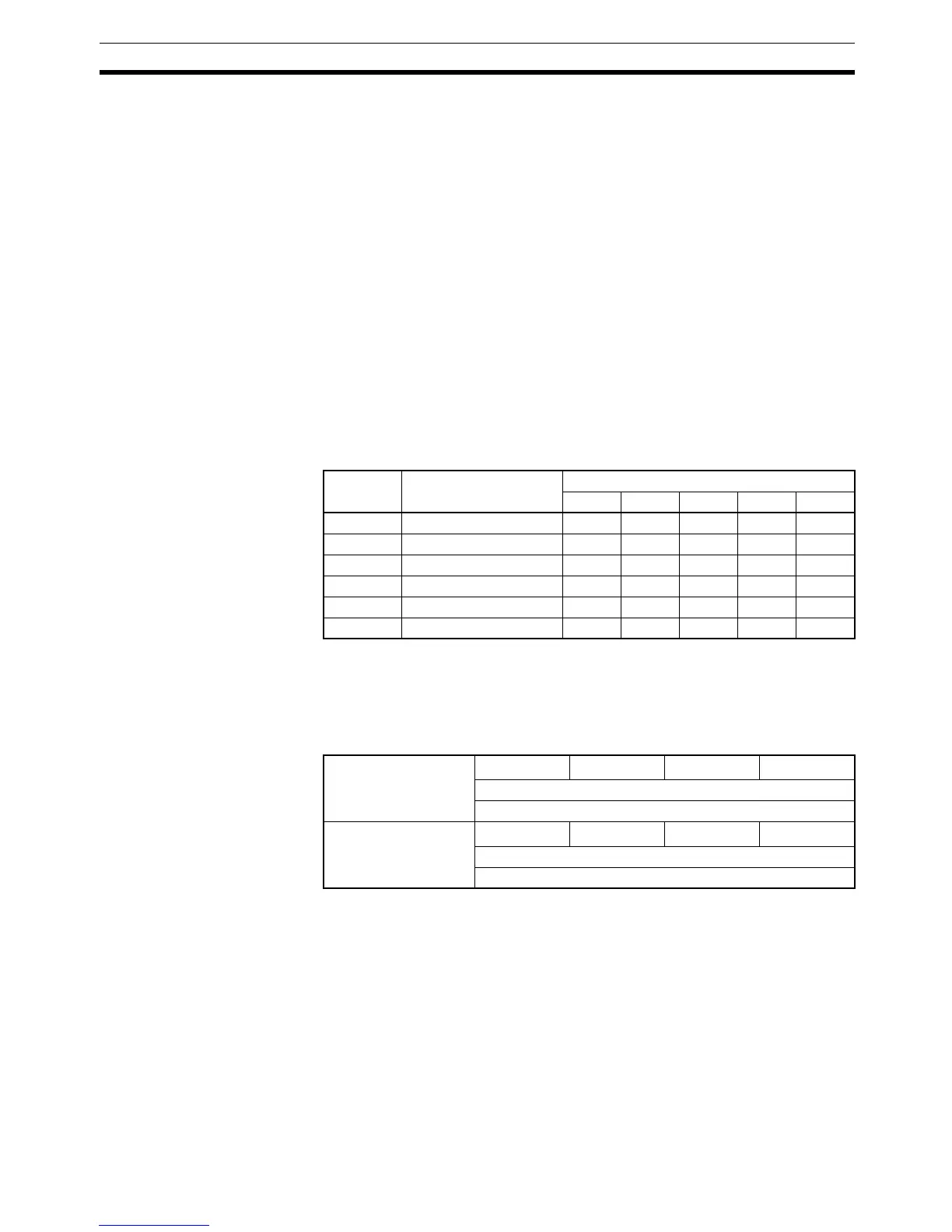
The following example shows the results of the write operation when a com-
munications error occurred while writing comparison value (H) in command
group 4.
• Response Monitor Area: Contains the error code.
• Comparison value (HH): The SV will be written normally.
• Comparison value (H): The SV won’t be written.
Offset Data Command group
12345
+0 Response monitor area Written Written Written Written Written
+1 Operation command --- --- Written --- Written
+2 and +3 Comparison value (HH) --- --- --- Written Written
+4 and +5 Comparison value (H) --- --- --- Written Written
+6 and +7 Comparison value (L) --- --- --- Written Written
+8 and +9 Comparison value (LL) --- --- --- Written Written
Offsets:
+2, 4, 6, 8
16
3
16
2
16
1
16
0
Write data lower byte (Binary, 2’s complement)
0000 to FFFF Hex
Offsets:
+3, 5, 7, 9
16
3
16
2
16
1
16
0
Write data upper byte (Binary, 2’s complement)
0000 to FFFF Hex