47
Unit Components Section 2-2
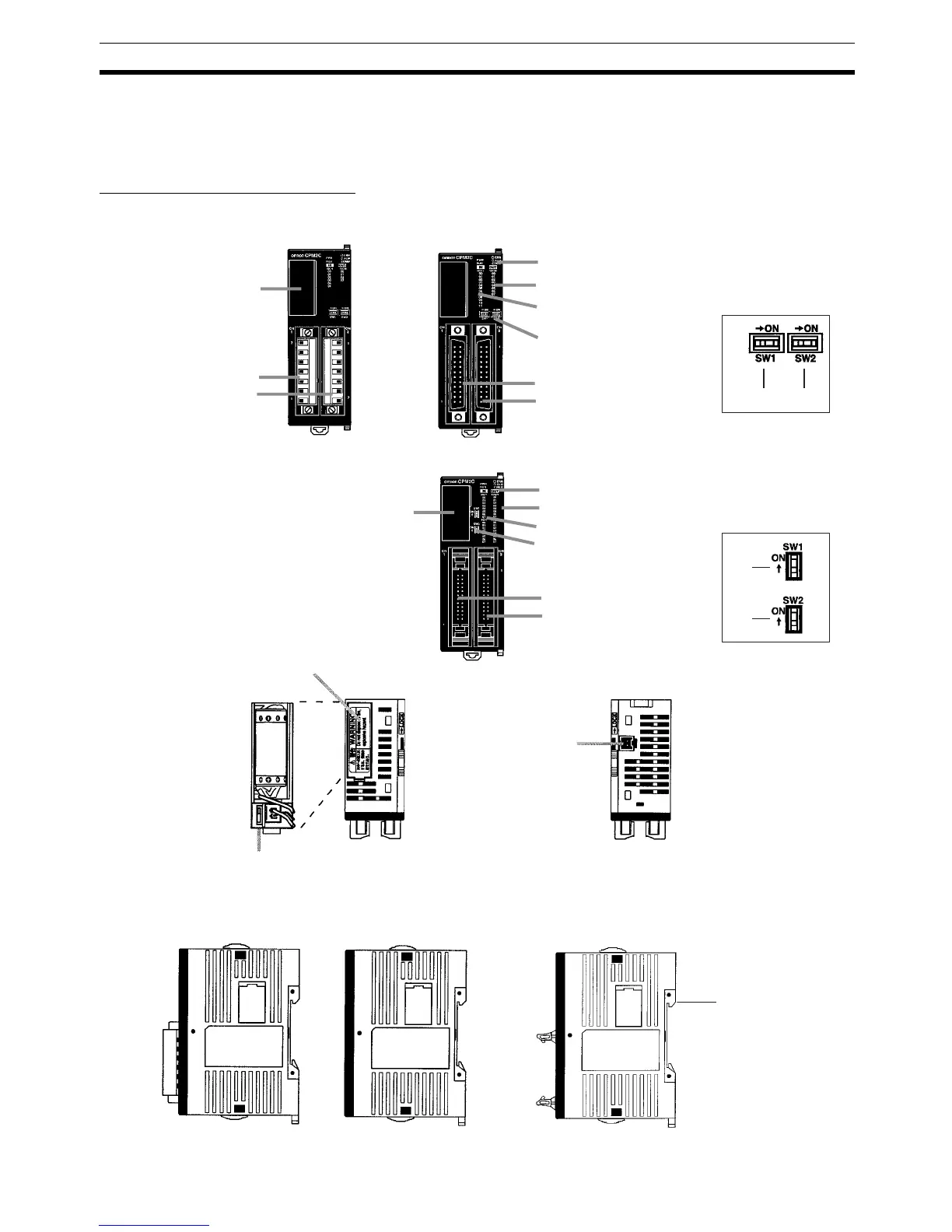
2-2 Unit Components
2-2-1 CPU Unit Components
CPU Unit Component Names
11. Low battery detection switch
10. Battery
Top View
Bottom View
Right Side:
Front View
2. Input terminals
7. Communications port
8. Communications switch
9. Customize switch
5. Input indicators
6. Output indicators
3. Output terminals
4. Status indicators
2. Input connector
3. Output connector
7. Communications port
8. Communications switch
9. Customize switch
5. Input indicators
6. Output indicators
4. Status indicators
2. Input connector
3. Output connector
(8) (9)
(8)
(9)
CPU Unit with Relay Out-
puts via Terminal Block
CPU Unit with Transistor Outputs
via Fujitsu-compatible Connector
DIP switch for Units
with 10/20 I/O points
CPU Unit with Transistor Outputs
via MIL Connector
DIP switch for Units
with 32 I/O points
1. Power supply
connector
CPU Unit with Relay
Outputs via Terminal
Block
CPU Unit with Transistor
Outputs via Fujitsu-compatible
Connector
CPU Unit with Transistor
Outputs via MIL Connector
12. Expansion I/O
connector
(output connector)