EasyManua.ls Logo

Omron CPM2C User Manual

Omron CPM2C
325 pages
To Next Page IconTo Next Page
To Previous Page IconTo Previous Page
Page #185 background imageLoading...
Page #185 background image
162
Programming Console Operations Section 4-2
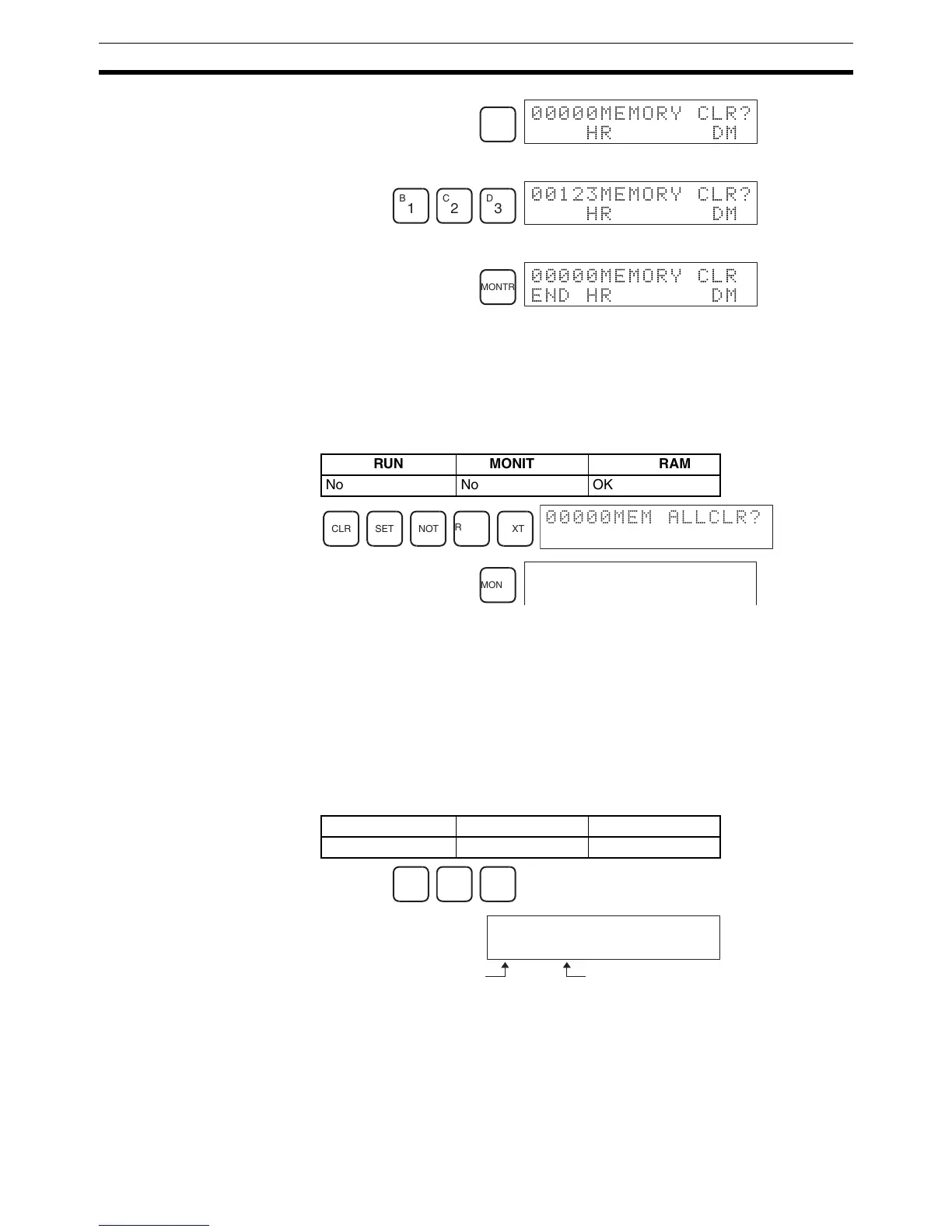
4. Press 123 to specify 123 as the starting program address.
5. Press the MONTR Key to clear the specified regions of memory.
4-2-3 Memory All Clear
With the upgrade from CX-Programmer version 1.2 to version 2.0, I/O com-
ments can be used with the CPM2A. Use the Memory All Clear operation to
delete data from the I/O comment area. All I/O memory area data will be
cleared by this operation and the area size will be set to the default value of
2.0 Kwords.
The Memory All Clear operation must be performed to clear the program
including the I/O comment area. The normal operation to clear memory will
not clear the I/O comment area.
4-2-4 UM Allocation Information Read
The UM allocation information can be read when an I/O comment area has
been set from the CX-Programmer (Ver. 2.0 or higher) to display the I/O com-
ment area and ladder program area sizes. Refer to the CX-Programmer Ver-
sion 2.0 (or higher) Operation Manual (W437) for information on changing the
size of the I/O comment area.
CNT
00000MEMORY CLR?
HR DM
B
1
C
2
D
3
00123MEMORY CLR?
HR DM
MONTR
00000MEMORY CLR
END HR DM
RUN MONITOR PROGRAM
No No OK
CLR SET NOT
RESET
EXT
00000MEM ALLCLR?
MONTR
00000MEM ALLCLR?
END
RUN MONITOR PROGRAM
OK OK OK
CLR FUN VER
CA LAD
02 04.1
I/O comment area: 2 Kwords
(2,048 is truncated for display.)
Ladder program area: 4.1 Kwords
(4,096 is truncated for display.)

Table of Contents

Question and Answer IconNeed help?

Do you have a question about the Omron CPM2C and is the answer not in the manual?

Omron CPM2C Specifications

General IconGeneral
TypeProgrammable Logic Controller (PLC)
Input Voltage24 VDC
Number of OutputsUp to 16
Communication PortsRS-232C
Programming LanguageLadder Logic
MountingDIN rail
CPUBuilt-in
Timer/Counter256 timers/counters
Analog InputOptional
Analog OutputOptional
Storage Temperature-25°C to 70°C
Memory4K words
Program Memory4K words
Humidity25 to 85% RH (non-condensing)

Summary

PRECAUTIONS

Safety Precautions

Critical safety warnings regarding grounding, live components, and external circuit safety measures.

Application Precautions

Crucial safety guidelines for system applications, emphasizing risk assessment and proper product use.

Operating Environment Precautions

Lists unsuitable locations and requirements for shielding against noise and environmental factors.

SECTION 1 Introduction

1-1 CPM2C Features and Functions

Introduces the CPM2C's special features, functions, system configurations, and capabilities.

1-2 System Configurations

Details possible system configurations, including CPU units, expansion units, and I/O units.

1-3 Structure and Operation

Explains CPU Unit internal structure, operating modes, and startup behavior.

1-6 Preparation for Operation

Outlines essential steps for initial system setup and Programming Console operation.

SECTION 2 Unit Components and Specifications

2-1 Specifications

Provides detailed technical specifications, including general, I/O, and power supply unit specs.

2-2 Unit Components

Describes physical components of CPU units, expansion I/O units, and various adapter units.

SECTION 3 Installation and Wiring

3-1 Design Precautions

Essential design considerations for power supply wiring, voltage, and safety circuits like interlocks.

3-3 Installing the CPM2C

Covers the procedure for installing the CPM2C unit and connecting expansion units.

3-4 Wiring and Connections

Provides fundamental information on wiring power supply, I/O terminals, connectors, and communication devices.

SECTION 4 Using a Programming Console

4-1 Using a Programming Console

Information on connecting and operating the Programming Console, including compatible models and mode switching.

4-2 Programming Console Operations

Details various operations like clearing memory, editing programs, searching, and monitoring functions.

4-3 Programming Example

Demonstrates writing a program using the console, including preparatory steps and a test run.

SECTION 5 Test Runs and Error Processing

5-1 Initial System Checks and Test Run Procedure

Outlines initial system checks, test runs, and flash memory precautions.

5-2 Self-diagnostic Functions

Explains error identification via messages, flags, and codes for accurate troubleshooting.

5-5 Troubleshooting Flowcharts

Provides visual flowcharts for diagnosing and resolving operational errors like power supply or I/O issues.

5-7 Battery Replacement

Details the procedure for replacing the backup battery with necessary safety warnings.

SECTION 6 Expansion Memory Unit

6-1 Overview

Introduces the Expansion Memory Unit, its memory areas, and general precautions for use.

6-2 Specifications and Nomenclature

Lists specifications and identifies components of the Expansion Memory Unit, including supported PCs and connectors.

6-3 Handling

Covers unit handling, including EEPROM mounting, PC connections, and program upload/download procedures.

SECTION 7 Simple Communications Unit

7-1 Introduction

Introduces the unit's features, system configuration, and component data processing methods.

7-3 Preparation for Operation

Details procedures for unit connections, switch settings, PC setup, and component configuration.

7-7 Error Processing

Explains detection and processing of fatal and non-fatal errors specific to the Simple Communications Unit.

7-9 Example Application

Demonstrates system configuration and DM settings for using the unit with temperature controllers.

Related product manuals