215
Handling Section 6-3
3. Gently hold down the EEPROM and pull down the lock lever.
Removing EEPROM Lift up the lock lever and detach the EEPROM.
6-3-2 PC Connections
!Caution Mount the EEPROM to the CPM1-EMU01-V1 before connecting the CPM1-
EMU01-V1 to the PC.
!Caution Do not disconnect the CPM1-EMU01-V1 from the PC when the indicator is
blinking green.
CPM2C and CQM1H PCs When connecting to the CPM2C or CQM1H, connect to the peripheral port via
the CPM2C-CN111 or CS1W-CN114 Connecting Cable. Also, set the pins on
the CPU Unit’s DIP switch as follows:
Note If pin 1 on the CPM2C or pin 5 on the CQM1H is OFF, connection is still pos-
sible if the peripheral port is set to the defaults.
CPM1, CPM1A, CPM2A,
CQM1, and SRM1 (-V2)
PCs
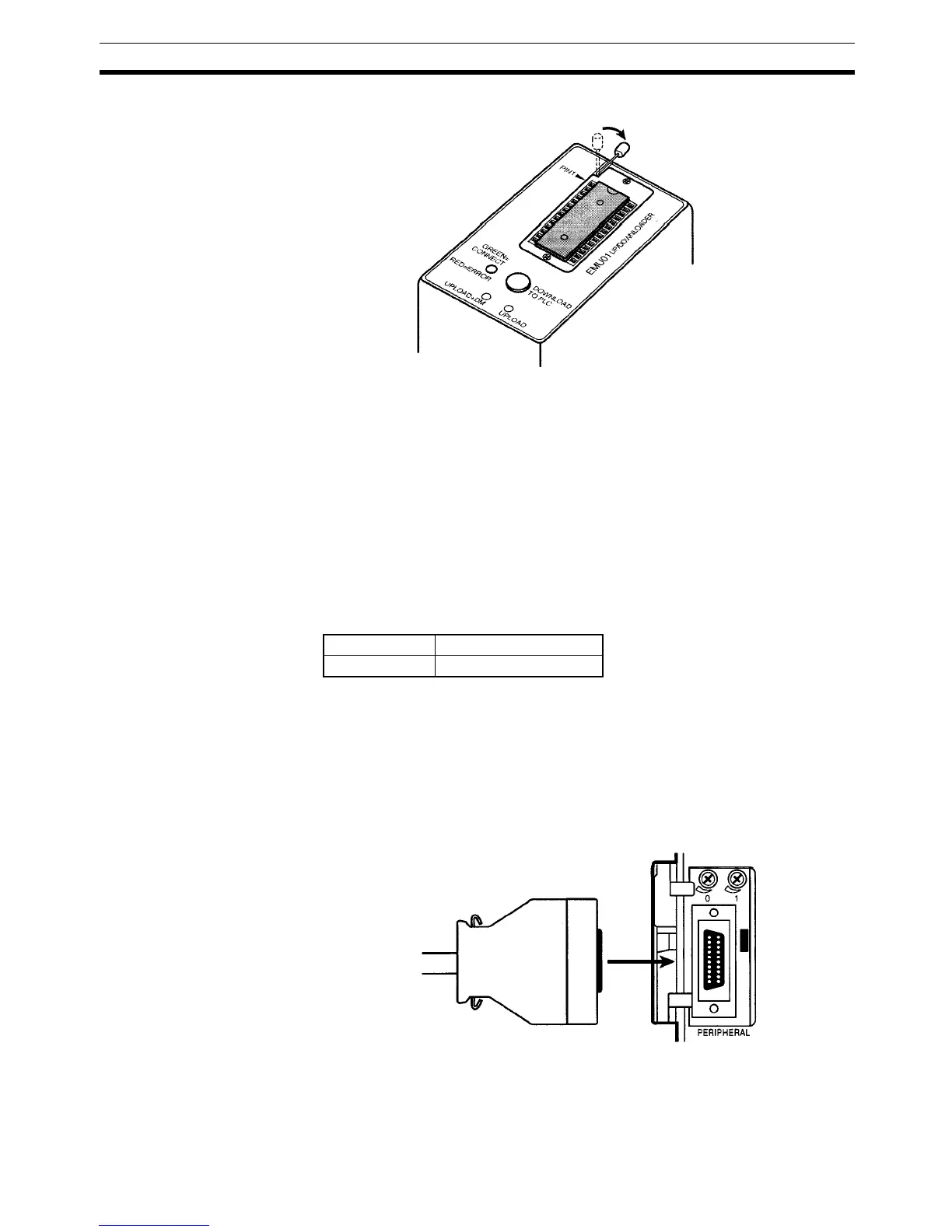
When connecting to the CPM1, CPM1A, CPM2A, CQM1 or SRM1 (-V2),insert
the connector into the peripheral port making sure that the connector is ori-
ented correctly.
• Insert the connector until it securely locks into place.
• Connections are not possible to the RS-232C port or any other port.
Peripheral Port
Communications Settings
The peripheral port must be set to the default communications settings shown
below.
Start bits: 1
Pull down the lock lever.
CPM2C Pin 1: ON (see note)
CQM1H Pin 5: ON (see note)