73
Unit Components Section 2-2
Units can be connected to a CPU Unit. Only 10 words, however, can be
allocated for input and output respectively.
A cover for the expansion I/O connector is not included with the Expansion
Unit. Use the cover included with the CPU Unit to cover the unused expan-
sion I/O connector on the last Expansion I/O Unit or Expansion Unit in the
PC.
6. Locking Lever
Used for securing Expansion Units.
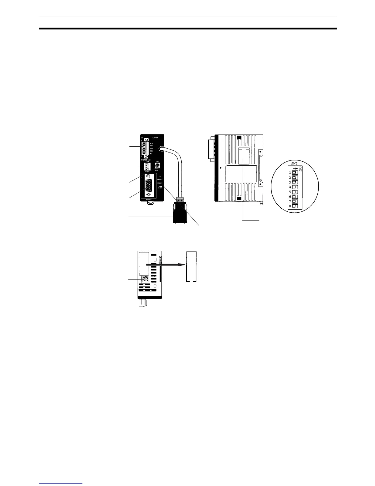
2-2-6 CPM2C-CIF21 Simple Communications Unit
Note The CPM2C-CIF21 can be used only with the CPM2C.
Front Side
1. RS-422/RS-485 port
4. RS-422/RS-485 switch (SW1)
6. DM area setting switch
2. RS-232C port
8. Connector
7. Status indicators
5. Communications switch (SW3)
Cover
3. Terminating resistance
switches (SW4)
Top
Use a flat-blade screwdriver
or similar device if the cover
is difficult to remove.