76
Unit Components Section 2-2
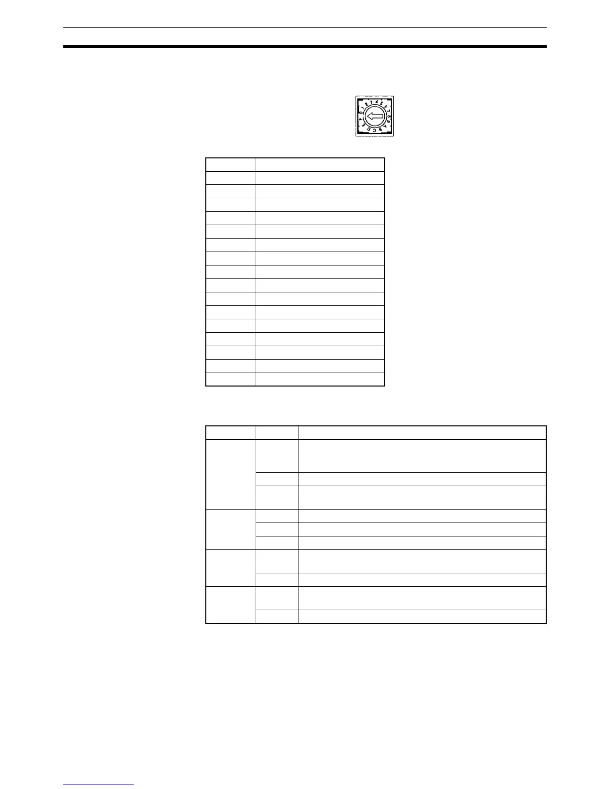
6. DM Area Setting Switch (SW2)
Sets the starting word in the DM Area
7. Status Indicators
Indicate the operating status of the Simple Communications Unit.
Setting Starting word in DM Area
0 DM 0000
1 DM 0100
2 DM 0200
3 DM 0300
4 DM 0400
5 DM 0500
6 DM 0600
7 DM 0700
8 DM 0800
9 DM 0900
A DM 1000
B DM 1100
C DM 1200
D DM 1300
E DM 1400
F DM 1500
Label Status Meaning
RUN Lit Communications established between Simple Communica-
tions Unit and CPU Unit. Simple Communications Unit oper-
ating.
Not lit Simple Communications Unit not operating.
Flashing Communications between Simple Communications Unit and
CPU Unit either not established or interrupted.
ERR/ALM Lit Fatal error occurred. (Unit operation stops.)
Flashing Non-fatal error occurred. (Unit operation continues.)
Not lit Unit operating normally.
COMM1 Flashing Transferring data between Simple Communications Unit and
CPU Unit
Not lit Not transferring data
COMM2 Flashing Transferring data between Simple Communications Unit and
connected components
Not lit Not transferring data