75
Unit Components Section 2-2
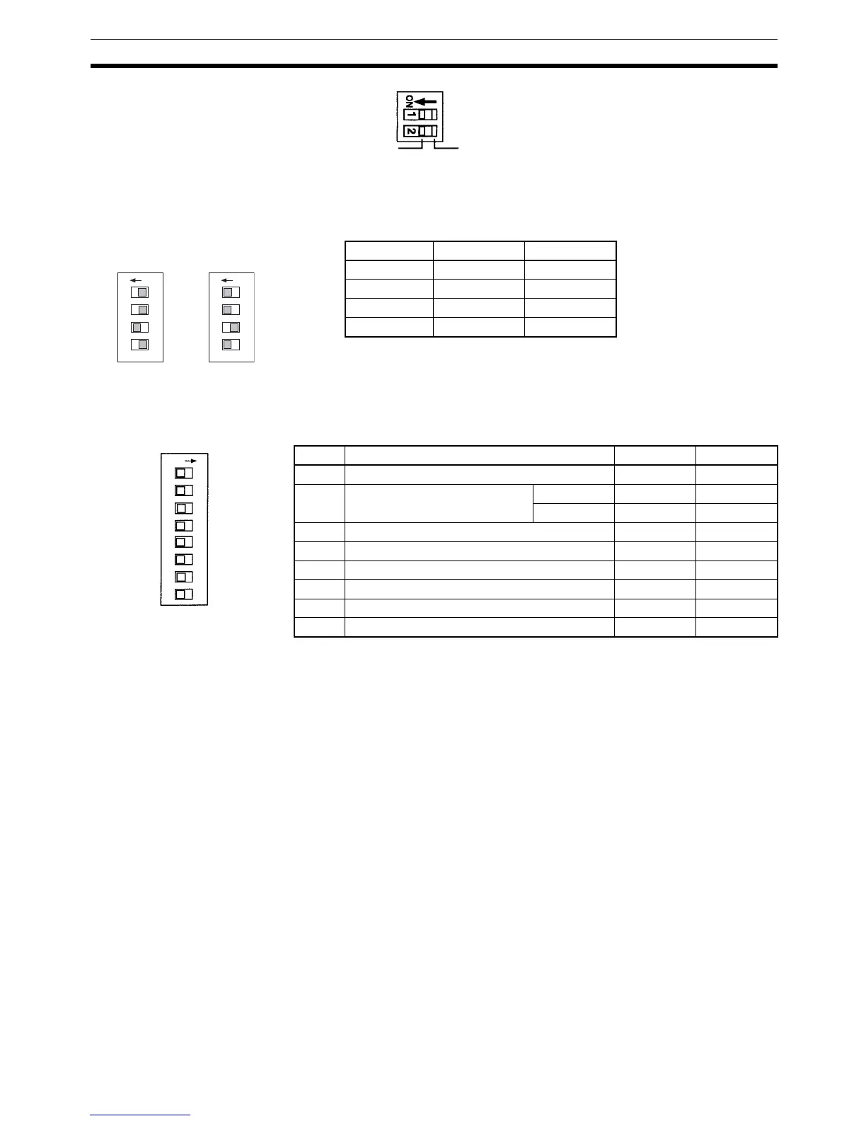
4. RS-422/RS-485 Switch (SW1)
Switches the RS-485 interface and sets RS/CS controls for the RS-485 in-
terface.
Note The default setting is for 2-wire RS-485 communications. Do not turn ON both
SW1-3 and SW1-4 at the same time. Doing so will destroy internal circuits.
5. Communications Switch (SW3)
Note a) Pins 3 to 6 on SW3 are used to set communications between gen-
eral-purpose communications components and the Simple Com-
munications Unit.
b) Turn OFF pin 7 on SW3. Operation may not be correct if this pin is
turned ON.
Pin on SW1 RS-422 RS-485
1OFFON
2OFFON
3ONOFF
4OFFON
Resistance
connected
Resistance
not connected
SW4
Terminating Resistance
RS-422: 235
Ω (combined
resistance must be 110
Ω min)
RS-485: 118
Ω (combined
resistance must be 54
Ω min)
ON 1 2 3 4
ON 1 2 3 4
SW1 SW1
RS-422 Setting RS-485 Setting
Pin Setting OFF ON
1 Baud rate with CPU Unit 9,600 bps 19,200 bps
2 Baud rate with components Normal 9,600 bps 19,200 bps
High-speed 38,400 bps 57,600 bps
3 Data length with components 7 bits 8 bits
4 Parity 1 setting with components Yes None
5 Parity 2 setting with components Even Odd
6 Stop bits with components 2 1
7 Not used. (Always leave pin 7 OFF.) Leave OFF. ---
8 Component communications speed Normal High-speed
O
N
1
2
3
4
All pins are turned
OFF at the factory.
SW3
5
6
7
8