109
Wiring and Connections Section 3-4
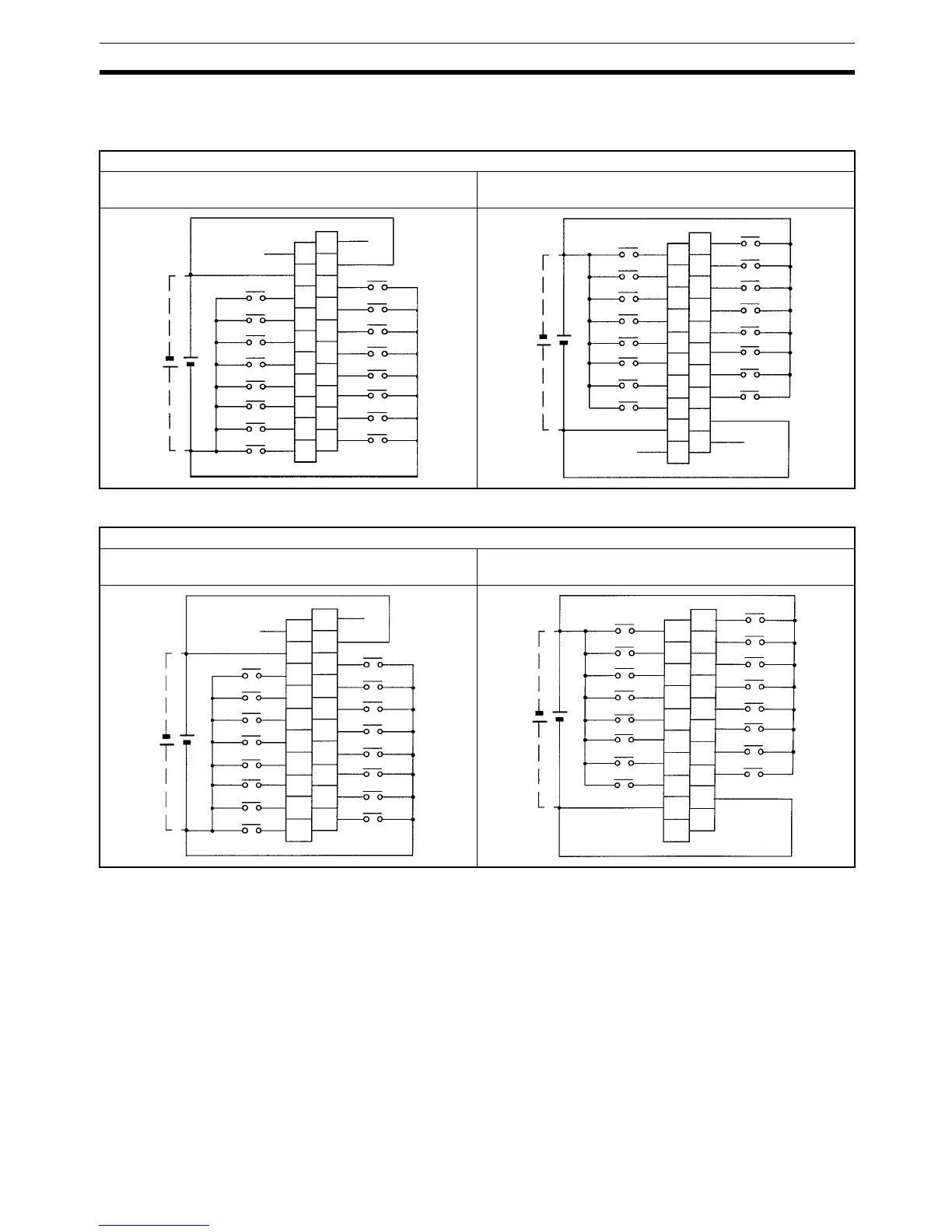
Note COM terminals (3 and 4) are connected internally.
Wiring Input Terminals The wiring for input terminals is as shown below.
Note For CPU Units with 32 I/O Points, relay numbers 00@00 to 00@07 correspond
to 00000 to 00007, relay numbers 00@08 to 00@15 correspond to 00100 to
00107, and relay numbers 01@00 to 01@07 correspond to 01000 to 01007,
and relay numbers 01@08 to 01@15 correspond to 01100 to 01107.
Terminal Blocks: XW2B-20G4, XW2B-20G5
Cable: XW2Z-@@@A (Fujitsu-compatible connector) Cable: G79-@C (Fujitsu-compatible connector),
G79-O@@C (MIL connector)
COM
00 07
00 06
00 05
00 04
00 03
00 02
00 01
00 00
COM
00 15
00 14
00 13
00 12
00 11
00 10
00 09
00 08
NC
NC
19
17
15
13
11
9
7
5
3
1
20
18
16
14
12
10
8
6
4
2
COM
00 07
00 06
00 05
00 04
00 03
00 02
00 01
00 00
COM
00 15
00 14
00 13
00 12
00 11
00 10
00 09
00 08
NC
NC
19
17
15
13
11
9
7
5
3
1
20
18
16
14
12
10
8
6
4
2
Terminal Blocks: XW2D-20G6
Cable: XW2Z-@@@A (Fujitsu-compatible connector) Cable: G79-@C (Fujitsu-compatible connector), G79-O@@C
(MIL connector)
COM
00 07
00 06
00 05
00 04
00 03
00 02
00 01
00 00
COM
00 15
00 14
00 13
00 12
00 11
00 10
00 09
00 08
NC
NC
A10
A9
A8
A7
A6
A5
A4
A3
A2
A1
B10
B9
B8
B7
B6
B5
B4
B3
B2
B1
COM
00 07
00 06
00 05
00 04
00 03
00 02
00 01
00 00
COM
00 15
00 14
00 13
00 12
00 11
00 10
00 09
00 08
NC
NC
A10
A9
A8
A7
A6
A5
A4
A3
A2
A1
B10
B9
B8
B7
B6
B5
B4
B3
B2
B1