EasyManua.ls Logo

Omron CPM2C User Manual

Omron CPM2C
325 pages
To Next Page IconTo Next Page
To Previous Page IconTo Previous Page
Page #190 background imageLoading...
Page #190 background image
167
Programming Console Operations Section 4-2
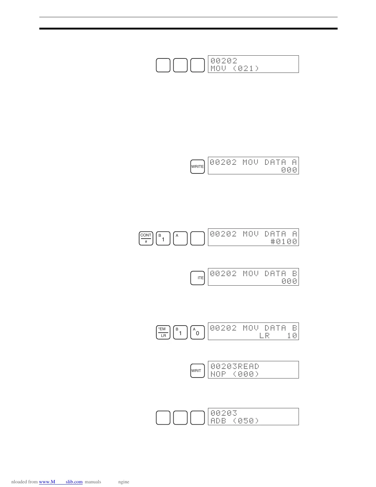
8. Input the third instruction and its operands. First input the instruction by
pressing the FUN Key and then the function code (21 in this case).
To input the differentiated version of an instruction, press the NOT Key af-
ter the function code (FUN 2 1 NOT). The “@” symbol will be displayed
next to differentiated instructions. Press the NOT Key again to change back
the instruction back to a non-differentiated instruction. The “@” symbol will
disappear.
To change an instruction after it has been entered, simply scroll through
the program until the desired instruction is displayed and press the NOT
Key. The “@” symbol should be displayed next to the instruction.
9. Press the WRITE Key to write the instruction to Program Memory. The in-
put display for the first operand will be displayed.
Writing Hexadecimal, BCD Constant
10. Input the first operand.
The operands of MOV (21) are normally word addresses, but a constant
can be input by pressing the CONT/# Key first. When the CONT/# Key is
pressed, the display will change to “#0000, indicating that a constant can
be entered.
Press the WRITE Key to write the instruction to Program Memory. The in-
put display for the second operand will appear.
Note The operands of MOV(21) can be word addresses, so the CONT/#
Key must be pressed to input a constant.
Writing a Word Address
11. Input the second operand.
Press the WRITE Key to write the instruction to Program Memory. The next
program address will be displayed.
Note When the default display value is “000”, a word address can be input
immediately without pressing the Shift and CH/# Keys.
12. Input the next instruction.
Press the WRITE Key to write the instruction to Program Memory.
FUN
C
2
B
1
00202
MOV (021)
WRITE
00202 MOV DATA A
000
CONT
#
B
1
A
0
A
0
00202 MOV DATA A
#0100
WRITE
00202 MOV DATA B
000
*EM
LR
B
1
A
0
00202 MOV DATA B
LR 10
WRITE
00203READ
NOP (000)
FUN
F
5
A
0
 !
),* #

Table of Contents

Question and Answer IconNeed help?

Do you have a question about the Omron CPM2C and is the answer not in the manual?

Omron CPM2C Specifications

General IconGeneral
TypeProgrammable Logic Controller (PLC)
Input Voltage24 VDC
Number of OutputsUp to 16
Communication PortsRS-232C
Programming LanguageLadder Logic
MountingDIN rail
CPUBuilt-in
Timer/Counter256 timers/counters
Analog InputOptional
Analog OutputOptional
Storage Temperature-25°C to 70°C
Memory4K words
Program Memory4K words
Humidity25 to 85% RH (non-condensing)

Summary

PRECAUTIONS

Safety Precautions

Critical safety warnings regarding grounding, live components, and external circuit safety measures.

Application Precautions

Crucial safety guidelines for system applications, emphasizing risk assessment and proper product use.

Operating Environment Precautions

Lists unsuitable locations and requirements for shielding against noise and environmental factors.

SECTION 1 Introduction

1-1 CPM2C Features and Functions

Introduces the CPM2C's special features, functions, system configurations, and capabilities.

1-2 System Configurations

Details possible system configurations, including CPU units, expansion units, and I/O units.

1-3 Structure and Operation

Explains CPU Unit internal structure, operating modes, and startup behavior.

1-6 Preparation for Operation

Outlines essential steps for initial system setup and Programming Console operation.

SECTION 2 Unit Components and Specifications

2-1 Specifications

Provides detailed technical specifications, including general, I/O, and power supply unit specs.

2-2 Unit Components

Describes physical components of CPU units, expansion I/O units, and various adapter units.

SECTION 3 Installation and Wiring

3-1 Design Precautions

Essential design considerations for power supply wiring, voltage, and safety circuits like interlocks.

3-3 Installing the CPM2C

Covers the procedure for installing the CPM2C unit and connecting expansion units.

3-4 Wiring and Connections

Provides fundamental information on wiring power supply, I/O terminals, connectors, and communication devices.

SECTION 4 Using a Programming Console

4-1 Using a Programming Console

Information on connecting and operating the Programming Console, including compatible models and mode switching.

4-2 Programming Console Operations

Details various operations like clearing memory, editing programs, searching, and monitoring functions.

4-3 Programming Example

Demonstrates writing a program using the console, including preparatory steps and a test run.

SECTION 5 Test Runs and Error Processing

5-1 Initial System Checks and Test Run Procedure

Outlines initial system checks, test runs, and flash memory precautions.

5-2 Self-diagnostic Functions

Explains error identification via messages, flags, and codes for accurate troubleshooting.

5-5 Troubleshooting Flowcharts

Provides visual flowcharts for diagnosing and resolving operational errors like power supply or I/O issues.

5-7 Battery Replacement

Details the procedure for replacing the backup battery with necessary safety warnings.

SECTION 6 Expansion Memory Unit

6-1 Overview

Introduces the Expansion Memory Unit, its memory areas, and general precautions for use.

6-2 Specifications and Nomenclature

Lists specifications and identifies components of the Expansion Memory Unit, including supported PCs and connectors.

6-3 Handling

Covers unit handling, including EEPROM mounting, PC connections, and program upload/download procedures.

SECTION 7 Simple Communications Unit

7-1 Introduction

Introduces the unit's features, system configuration, and component data processing methods.

7-3 Preparation for Operation

Details procedures for unit connections, switch settings, PC setup, and component configuration.

7-7 Error Processing

Explains detection and processing of fatal and non-fatal errors specific to the Simple Communications Unit.

7-9 Example Application

Demonstrates system configuration and DM settings for using the unit with temperature controllers.

Related product manuals