xxiii
EC Directives 6
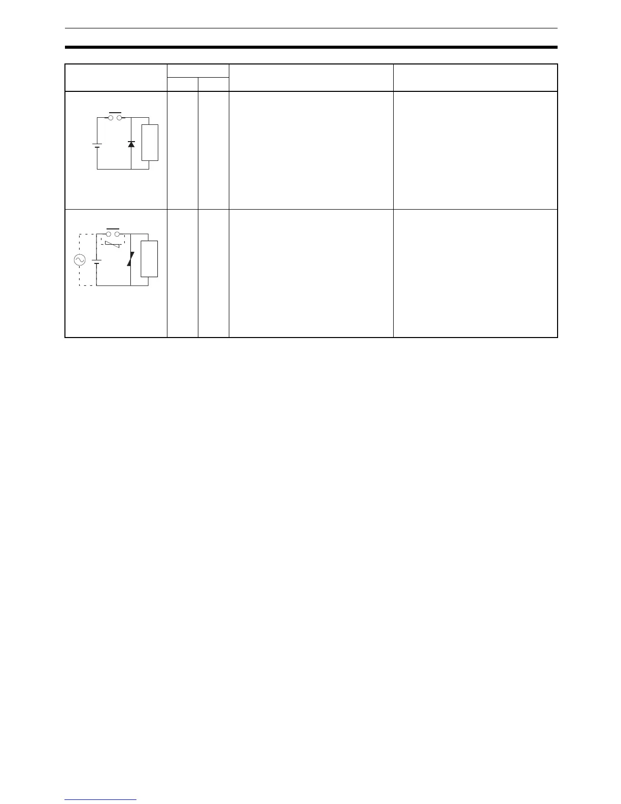
No Yes The diode connected in parallel with
the load changes energy accumulated
by the coil into a current, which then
flows into the coil so that the current
will be converted into Joule heat by the
resistance of the inductive load.
This time lag, between the moment the
circuit is opened and the moment the
load is reset, caused by this method is
longer than that caused by the CR
method.
The reversed dielectric strength value
of the diode must be at least 10 times
as large as the circuit voltage value.
The forward current of the diode must
be the same as or larger than the load
current.
The reversed dielectric strength value
of the diode may be two to three times
larger than the supply voltage if the
surge protector is applied to electronic
circuits with low circuit voltages.
Yes Yes The varistor method prevents the impo-
sition of high voltage between the con-
tacts by using the constant voltage
characteristic of the varistor. There is
time lag between the moment the cir-
cuit is opened and the moment the load
is reset.
If the supply voltage is 24 to 48 V,
insert the varistor in parallel with the
load. If the supply voltage is 100 to
200 V, insert the varistor between the
contacts.
---
Circuit Current Characteristic Required element
AC DC
Diode method
Power
supply
Inductive
load
Varistor method
P