226
Introduction Section 7-1
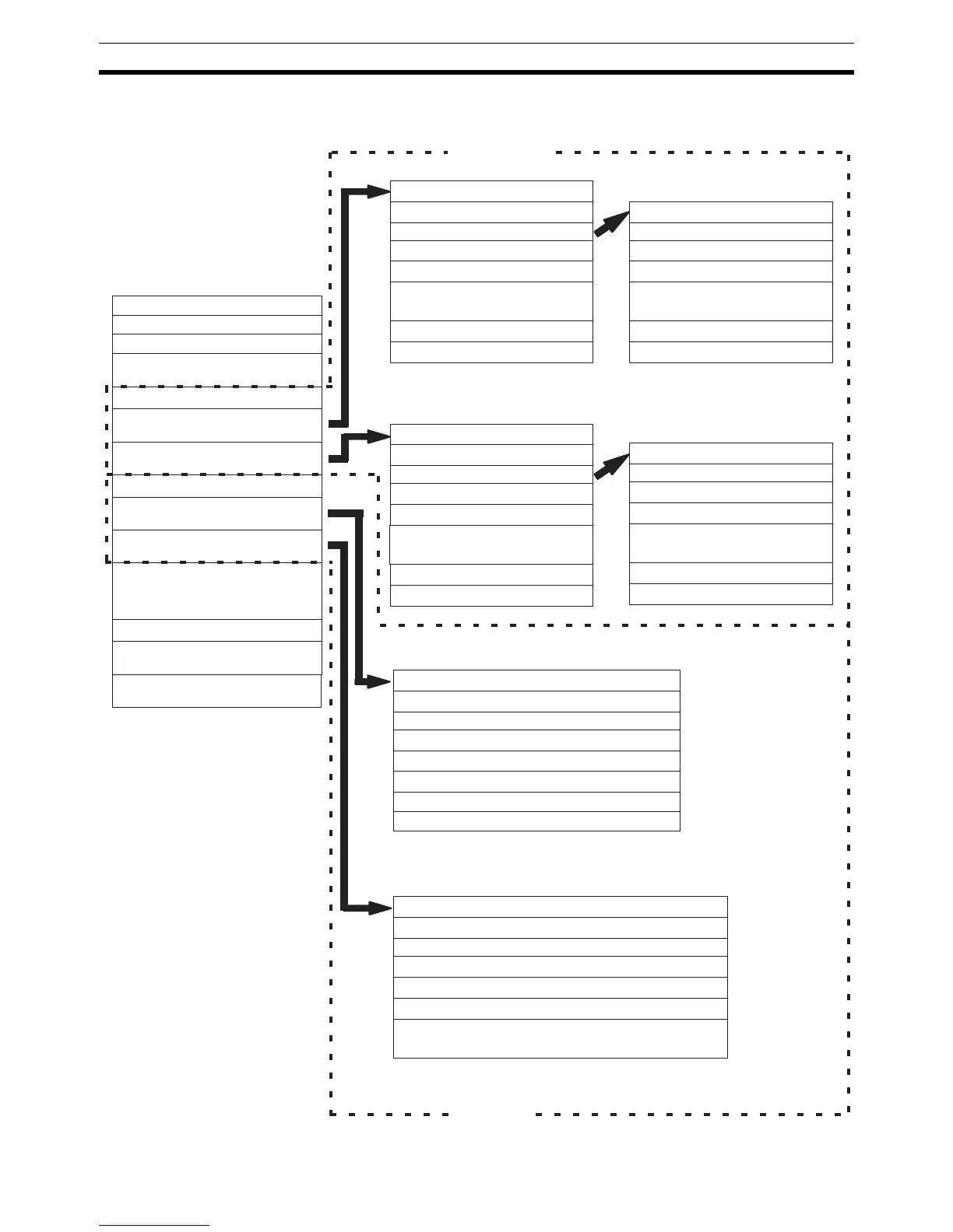
Data Memory Structure The following diagram shows the structure of the DM area used for communi-
cations through the Simple Communications Unit.
Read variable type area
Number of read items
Reserved
Starting address of read data area
Variable 1 type
Variable 1 address
:
Variable 12 type
Variable 12 address
Write variable type area
Number of write items
Operation command
Starting address of write data area
Variable 1 type
Variable 1 address
:
:
Variable 12 type
Variable 12 address
Read data area
Write data area
Response monitor
Component status
Variable 1 read data (lower bytes)
Variable 1 read data (upper bytes)
:
:
Variable 12 read data (lower bytes)
Variable 12 read data (upper bytes)
Response monitor
Operation command
Variable 1 write data (lower bytes)
Variable 1 write data (upper bytes)
:
:
Variable 12 write data (lower bytes)
Variable 12 write data (upper bytes)
Read data area
Response monitor
Present temperature (Display value (lower bytes))
Status (Display value (upper bytes))
Target temperature (Status)
Alarm 1 SV (Peak hold setting (lower bytes))
Alarm 2 SV (Peak hold setting (upper bytes))
Proportional band (Status)
Note The values in parentheses show the read
data for Digital Panel Meters.
Write data area
Response monitor
Target temperature (Operation Command)
Operation command (Comparison value HH (lower bytes))
Alarm 1 SV (Comparison value HH (upper bytes))
Alarm 2 SV (Comparison value H (lower bytes))
Proportional band (Comparison value H (upper bytes))
:
:
Note The values in parentheses show the write
data for Digital Panel Meters.
Control data area
Simple Communications Unit control
Simple Communications Unit status
Syntax error address
Unit number 0 to 31
communications control
Unit 0 communications type
Starting address of Unit 0
read variable type area
Starting address of Unit 0
write variable type area
Unit 1 communications type
Starting address of Unit 1
read data area
Starting address of Unit 1
write data area
:
:
:
Unit 31 communications type
Starting address of Unit 31
read variable type area
CompoWay/F
SYSWAY
:
:
Starting address of Unit 31write
variable type area
Starting address of separate area
(103 words)
(27 words max.)
(26 words max.)
(27 words max.)
(26 words max.)
(11 words, 18 words for Digital
Panel Meter)
(9 words, 10 words for Digital
Panel Meter)