249
Data Memory (DM) Allocation Section 7-4
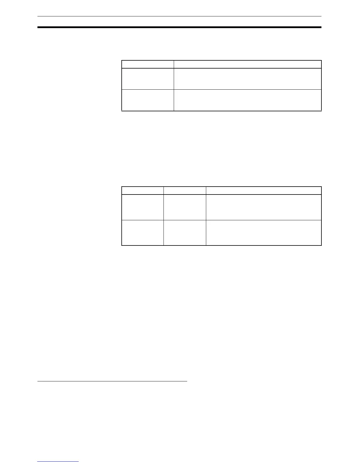
Operation Command (Offset: +1)
Refer to the component’s Operation Manual for details on the command
codes for the various CompoWay/F communications functions.
Note 1. SVs cannot be written in a scan in which “start auto-tuning” has been spec-
ified.
2. Execute commands to select the RAM write mode and backup mode in
only one scan. Some devices will write to non-volatile memory each time
the modes are selected, and the life of the non-volatile memory will be ex-
hausted much more quickly if selections are made every scan.
Write Data (Offset: +2, +4, ... , +22, and +24)
The write data is contained in two words starting at offset 2
× n (n = variable
number.)
If a communications error occurs, the write operation that is in progress will be
stopped and the next process will be performed for the general-purpose com-
munications device.
The following example shows the results of the write operation when a com-
munications error occurred while writing variable 2.
• Response Monitor Area: Contains the error code.
• Operation Command: The operation command won’t be executed.
• Variable 1 write data: The SV will be written normally.
• Variable 2 write data: The SV won’t be written.
• Remaining write items: SVs won’t be written.
Note 1. The decimal point position has to be managed by the user since the com-
ponent’s decimal point position is not transferred in CompoWay/F commu-
nications.
2. BCD format is used with Digital Panel Meters (K3N@). For details, refer to
the manual for the model used.
Area Structure for SYSWAY Communications
Read Data Area:
Temperature Controllers
(11 words)
The following data will be read from a Temperature Controller when host link
has been specified as the component communications protocol.
The starting address of the “read data area” is specified in the “control data
area.” Select any one of the 5 command groups to specify which PVs and SVs
Bits Function
0 to 7
(Digits 16
0
and 16
1
)
Related information
Set any related information required by the CompoWay/F
command code as described in the component’s manual.
8 to 15
(Digits 16
2
and 16
3
)
Command code
Set the CompoWay/F command code as described in the
component’s manual.
Offset Range Function
2 × n
(n = variable
number)
0000 to FFFF
(Hex)
Store the lower (rightmost) two bytes of the SV
data that you want to write to the corresponding
component. Data is expressed in 2’s comple-
ment signed binary format.
(2 × n) + 1
(n = variable
number)
0000 to FFFF
(Hex)
Store the upper (leftmost) two bytes of the SV
data that you want to write to the corresponding
component. Data is expressed in 2’s comple-
ment signed binary format.