250
Data Memory (DM) Allocation Section 7-4
will be read, although 11 DM words will be allocated to the read data area
regardless of the command group selected.
Response Monitor Area (Offset: +0)
The structure of the response monitor area is the same whether SYSWAY or
CompoWay/F communications are used. See Response Monitor Area on
page 246 for details on the response monitor area.
Read Data (Offset: +1, +3, +4, +5, +6, +7, +8, and +9)
Each word of data read from the Temperature Controller has a value ranging
from 0000 to FFFF, which is 2’s complement signed binary data. The word will
contain 0000 if a communications error occurred. The following example
shows the contents of the read data when a communications error occurred
while reading the target temperature in command group 1.
• Response Monitor Area: Contains the error code.
• Present temperature: Contains data read from Temperature Controller.
• Status: Contains status read from Temperature Control-
ler.
• Target temperature: Contains 0000.
Note The decimal point position has to be managed by the user since the Tempera-
ture Controller’s decimal point position is not transferred in host link (X format)
communications.
Status (Offset: +2 and +10)
The read data area’s +2 offset word contains the status when reading the
present temperature. The +10 offset word contains the heater current status
when reading the heater current. Refer to the Temperature Controller’s Opera-
tion Manual for details on the status values.
Read Data Area:
Digital Panel Meters
(18 words)
The following data will be read from a Digital Panel Meter when SYSWAY has
been specified as the component communications protocol.
The starting address of the “read data area” is specified in the “control data
area.” Select any one of the 5 command groups to specify which PVs and SVs
will be read, although 18 DM words will be allocated to the read data area
regardless of the command group selected.
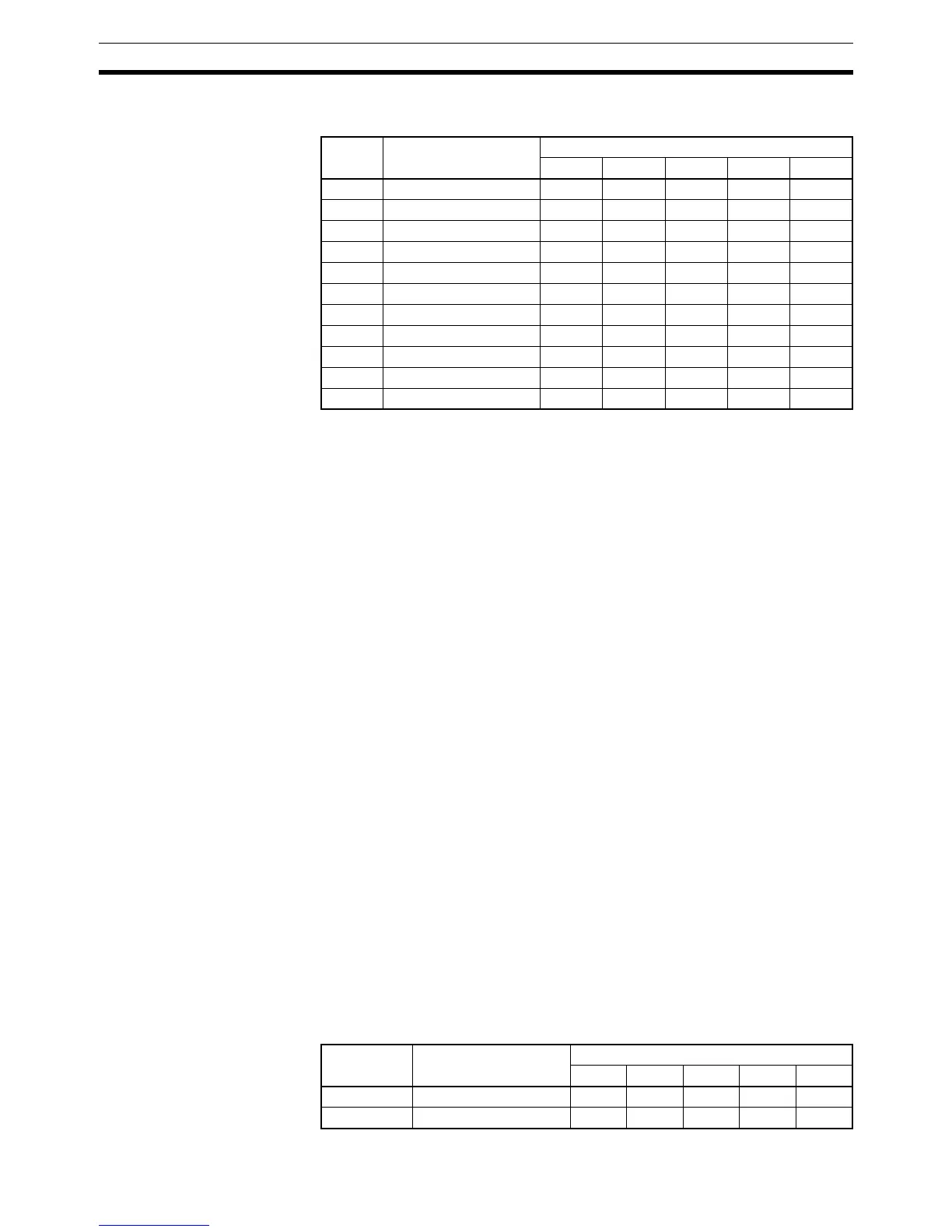
Offset Data Command group
12345
+0 Response monitor Read Read Read Read Read
+1 Present temperature Read Read Read Read Read
+2 Status Read Read Read Read Read
+3 Target temperature Read Read Read Read Read
+4 Alarm 1 SV --- --- Read Read Read
+5 Alarm 2 SV --- --- Read Read Read
+6 Proportional band --- --- --- Read Read
+7 Reset time --- --- --- Read Read
+8 Derivative time --- --- --- Read Read
+9 Heater current monitor --- --- --- --- Read
+10 Heater current status --- --- --- --- Read
Offset Data Command group
1234*5
+0 Response monitor area Read Read Read Read Read
+1 and +2 Display value Read Read Read Read Read