3 Specifications
3 - 76
OMNUC G5-series (Pulse-train Input Type) AC Servomotors and Servo Drives User’s Manual
Cable types
200 V:
(For 3,000-r/min Servomotors of 1 to 2 kW, 2,000-r/min Servomotors of 1 to
2 kW, 1,000-r/min Servomotors of 900 W)
*1 For information on minimum bending radius, refer to 3-5-1 Resistance to Bending of Global Flexible Cable on
page 3-62.
Connection configuration and external dimensions
Wiring
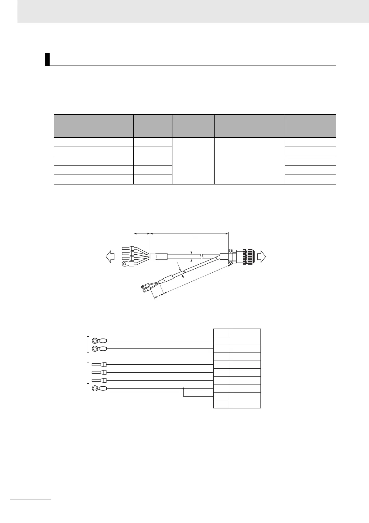
Power Cables with Brake: Global Flexible Cable (R88A-CAGBBR)
Model Length (L)
Outer
diameter of
sheath
Minimum bending
radius (R)
*1
Weight
R88A-CAGB003BR 3 m 12.7 dia./
6.1 dia.
Power cable part: 90 mm
Brake cable part: 45 mm
Approx. 0.9 kg
R88A-CAGB005BR 5 m Approx. 1.5 kg
R88A-CAGB010BR 10 m Approx. 2.8 kg
R88A-CAGB015BR 15 m Approx. 4.2 kg
R88A-CAGB020BR 20 m Approx. 5.5 kg
L
(70)
(ø12.7)
(70)
(ø6.1)
L
Servo Drive side
Servomotor side
R88D-KP
R88M-KE
Servo Drive side
Black
White
Red
White
Blue
Green/Yellow
Cable:
AWG20 × 2C UL2464
Cable:
AWG14 × 4C UL2501
[Servomotor side connector]
Straight plug model
N/MS3106B20-18S (Japan Aviation Electronics)
Cable clamp model
N/MS3057-12A (Japan Aviation Electronics)
M4 crimp
terminal
Ferrule
M4 crimp
terminal
No.
G
H
A
F
Brake
Brake
Phase U
Phase V
Phase W
NC
Symbol
I
B
E
D
C
FG
FG
NC
Servomotor side

 Loading...


