3 - 91
3 Specifications
OMNUC G5-series (Pulse-train Input Type) AC Servomotors and Servo Drives User’s Manual
3-5 Cable and Connector Specifications
3
3-5-6 Control Cable Specifications
This connector terminal block cable is connected to the Servo Drive’s control I/O connector (CN1). All of
the pins in the control I/O connector (CN1) can be converted to terminals on the terminal block.
Cable types
Connection configuration and external dimensions
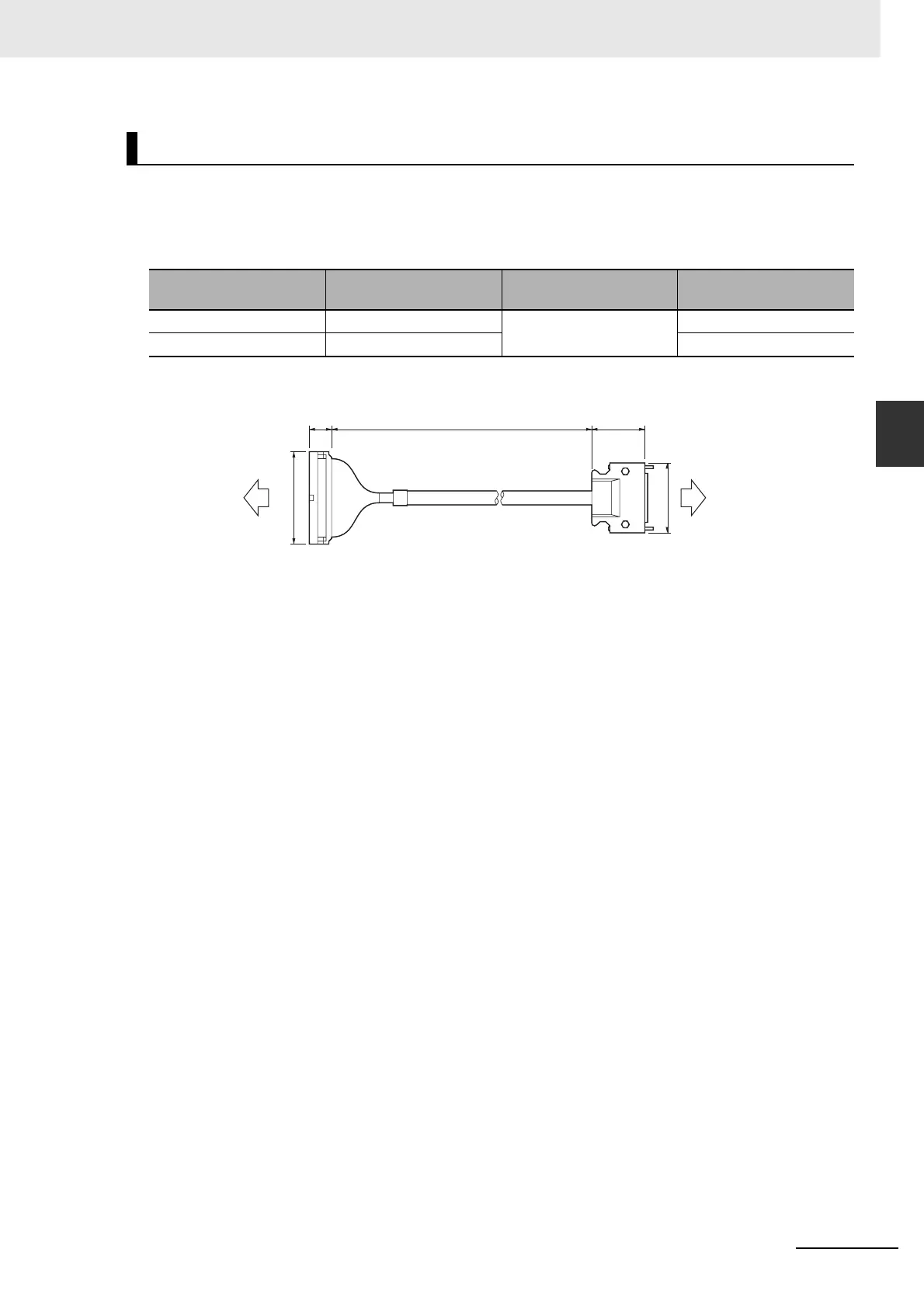
Connector Terminal Block Cables (XW2Z-J-B24)
Model Length (L)
Outer diameter of
sheath
Weight
XW2Z-100J-B24 1 m 11.2 dia. Approx. 0.2 kg
XW2Z-200J-B24 2 m Approx. 0.4 kg
39L16.1
Connector Terminal
Block side
XW2B-50G4
XW2B-50G5
XW2D-50G6
68.1
t = 18t = 6.1
Servo Drive side
R88D-KP
52.4

 Loading...


