3 Specifications
3 - 92
OMNUC G5-series (Pulse-train Input Type) AC Servomotors and Servo Drives User’s Manual
No.
1
2
3
4
5
6
7
8
9
10
11
20
21
22
23
24
26
27
28
29
30
31
32
33
34
37
38
35
36
39
40
41
42
43
44
45
46
47
48
49
50
No.
1
2
3
4
5
6
7
8
9
10
11
20
21
22
23
24
26
27
28
29
30
31
32
33
34
37
38
35
36
39
40
41
42
43
44
45
46
47
48
49
50
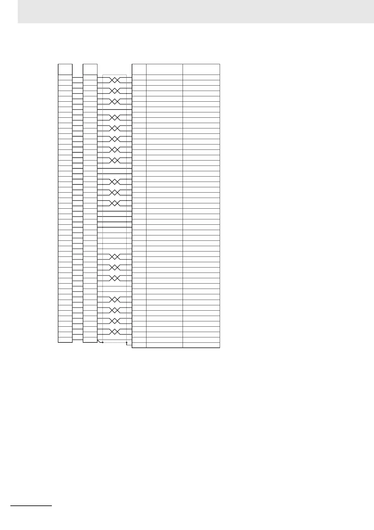
Terminal
block
Connector
Color of wire/
mark
No.
Symbol
1 +24VCW
2 +24VCCW
3
4
–CW/–PULS/–FA
5
6
7 +24VIN
SO1+
8SI1
SI2
SO1–
9
10
11
20
21 +A
22 –A
+Z
–Z
23
24
SI3
26
27 SI4
28 SI5
29 SI6
30 SI7
31
32 SI9
SI8
33 SI10
34 SO2–
37 /ALM
38 SO3–
35 SO2+
36 ALMCOM
39
SO3
+
40
– – –
41
– – –
42
– – –
43
– – –
44 +CWLD
45 –CWLD
46 +CCWLD
47 –CCWLD
48 –B
49 +B
50
– – –
Shell
FG
Servo Drive side
+CW/+PULS/+FA
+CCW/+SIGN/+FB
–CCW/–SIGN/–FB
1313 SGGND13
1212
– – –
12
14
15
16
17
18
19
14
15
16
17
18
19
14
SGGND
SGGND
15
16
17
18
19 Z
2525 SGGND25
– – –
– – –
– – –
– – –
Blue/Red (1)
Blue/Black (1)
Pink/Red (1)
Pink/Black (1)
Green/Red (1)
Green/Black (1)
Orange/Red (1)
Gray/Red (1)
Gray/Black (1)
Blue/Red (2)
Blue/Black (2)
Pink/Red (2)
Pink/Black (2)
Green/Red (2)
Green/Black (2)
Orange/Red (2)
Orange/Black (2)
Gray/Red (2)
Gray/Black (2)
Blue/Red (3)
Blue/Black (3)
Pink/Red (3)
Pink/Black (3)
Green/Red (3)
Green/Black (3)
Orange/Red (3)
Orange/Black (3)
Gray/Red (3)
Gray/Black (3)
Blue/Red (4)
Blue/Black (4)
Pink/Red (4)
Pink/Black (4)
Green/Red (4)
Green/Black (4)
Orange/Red (4)
Orange/Black (4)
Gray/Red (4)
Gray/Black (4)
Blue/Red (5)
Blue/Black (5)
Pink/Red (5)
Pink/Black (5)
Green/Red (5)
Green/Black (5)
Orange/Red (5)
Orange/Black (5)
Gray/Red (5)
Gray/Black (5)
Orange/Black (1)
• Wires with the same wire color and the
same number of marks form a twisted pair.
Example:The wire described as Yellow/
Black (1) and that described as Pink/
Black (1) are paired and twisted
together.
Drive connector
Connector plug model
10150-3000PE (Sumitomo 3M)
Connector case model:
10350-52A0-008 (Sumitomo 3M)
Connector terminal block connector
Connector socket model:
XG4M-5030 (OMRON)
Strain relief model:
XG4T-5004 (OMRON)
Cable
AWG28 x 25P UL2464

 Loading...


