3 - 93
3 Specifications
OMNUC G5-series (Pulse-train Input Type) AC Servomotors and Servo Drives User’s Manual
3-5 Cable and Connector Specifications
3
3-5-6 Control Cable Specifications
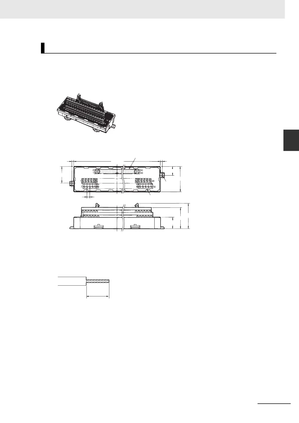
The Connector Terminal Block Conversion Unit is used in combination with a Connector Terminal Block
Cable (Model: XW2Z-J-B24) to convert the Servo Drive’s control I/O connector (CN1) to the terminal
block.
XW2B-50G4 (M3 Screw Terminal Block)
• External Dimensions
• Use 0.3 to 1.25 mm
2
wire (AWG22 to 16).
• The wire inlet is 1.8 mm (height) x 2.5 mm (width).
• Strip the insulation from the end of the wire as shown below.
Connector Terminal Block Conversion Unit
Flat cable connector (MIL-type plug)
3.5
15.5
45
2-φ3.5
Terminal block
3.5
29.5
5.08
20.5
38.1
(45.3)
157.5
6 mm

 Loading...


