3 - 113
3 Specifications
OMNUC G5-series (Pulse-train Input Type) AC Servomotors and Servo Drives User’s Manual
3-6 Servo Relay Unit and Cable Specifications
3
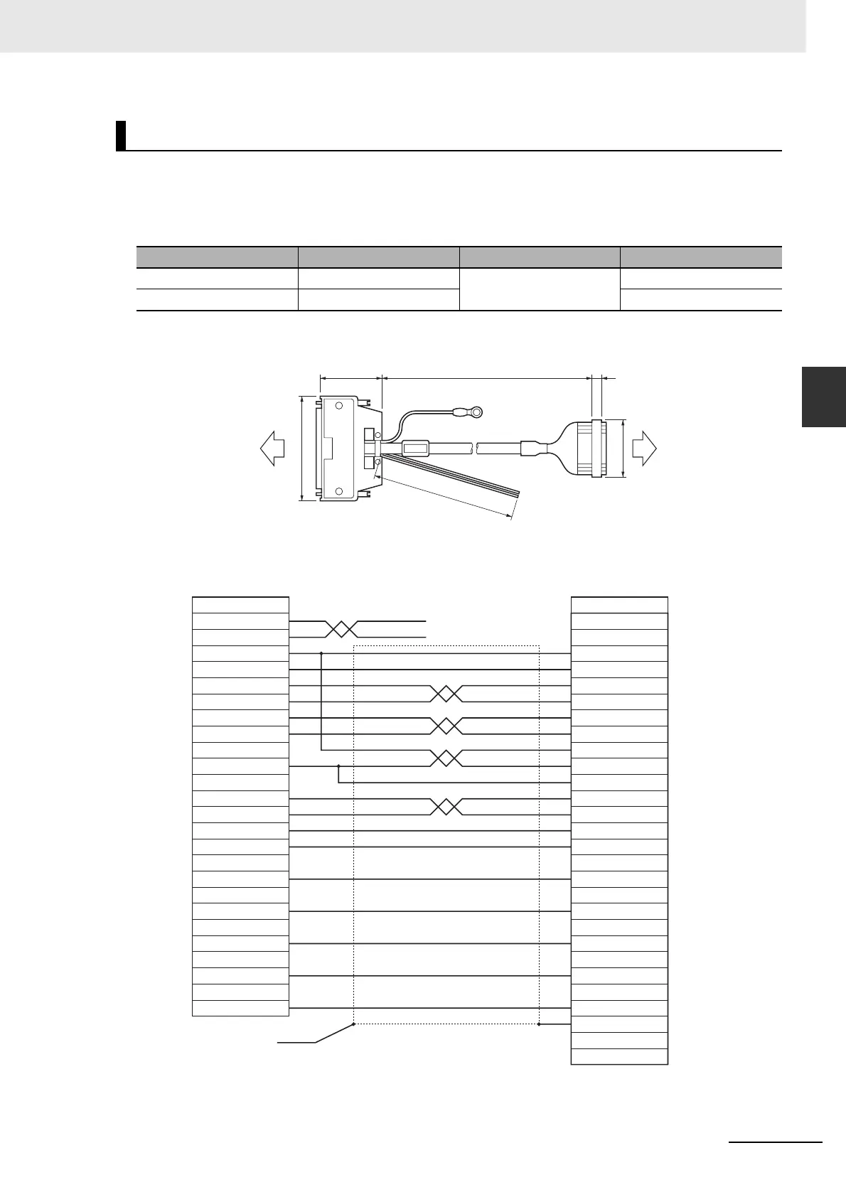
3-6-3 Position Control Unit Relay Unit Cable Specifications
Below are the specifications of the cable that connects a Position Control Unit (Model: CS1W-NC133)
with a Servo Relay Unit (Model: XW2B-20J6-1B).
Cable types
Connection configuration and external dimensions
Wiring
Position Control Unit Cables (XW2Z-J-A10)
Model Length (L)
Outer diameter of sheath
Weight
XW2Z-050J-A10 50 cm 10.0 dia. Approx. 0.1 kg
XW2Z-100J-A10 1 m Approx. 0.2 kg
48
L647
83
t=11
1000
CS1W-NC133 XW2B-20J6-1B
Position Control Unit side Servo Relay Unit side
No.
1
2
3
4
5
6
7
8
9
10
11
12
13
14
15
16
17
18
19
20
21
22
23
26
No.
A1
A2
A7
A8
A5
A6
A10
A24
A12
A16
A14
A21
A23
24
25
A20
A19
A22
A3
A4
Cable: AWG28×4P+AWG28×10C
Position Control Unit side
AWG20 Black
AWG20 Red
Servo Relay Unit side
Crimp terminal

 Loading...


