4 - 37
4 System Design
OMNUC G5-series (Pulse-train Input Type) AC Servomotors and Servo Drives User’s Manual
4-3 Wiring Conforming to EMC Directives
4
4-3-2 Selecting Connection Components
This section explains the criteria for selecting the connection components required to improve noise
resistance.
Understand each component’s characteristics, such as its capacity, performance, and applicable range
when selecting the connection components.
For more details, contact the manufacturers directly.
Noise Filters for Motor Output
• Use noise filters without built-in capacitors on the motor output lines.
• Select a noise filter with a rated current at least twice the Servo Drive’s continuous output current.
• The following table shows the noise filters that are recommended for motor output lines.
Note 1 Motor output lines cannot use the same noise filters for power supplies.
2 General noise filters are made for power supply frequencies of 50/60 Hz. If these noise filters are
connected to PWM output of the Servo Drive, a very large (about 100 times larger) leakage current may
flow through the noise filter’s capacitor. This may damage the Servo Drive.
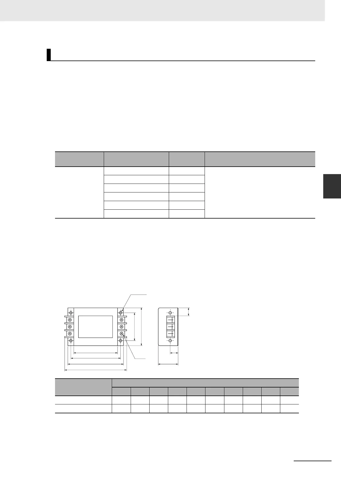
External Dimensions
3G3AX-NF001/-NF002
Selecting Other Parts for Noise Resistance
Manufacturer Model
Rated
current
Comment
OMRON 3G3AX-NF001 6 A For inverter output
3G3AX-NF002 12 A
3G3AX-NF003 25 A
3G3AX-NF004 50 A
3G3AX-NF005 75 A
3G3AX-NF006 100 A
Model
Dimensions [mm]
A B C E F G H J M P
3G3AX-NF001 140 125 110 70 95 22 50 20 ø4.5 156
3G3AX-NF002 160 145 130 80 110 30 70 25 ø5.5 176
4-M
M4
C
B
A
P
E
F
J
H
G

 Loading...


