5 Basic Control Mode
5 - 4
OMNUC G5-series (Pulse-train Input Type) AC Servomotors and Servo Drives User’s Manual
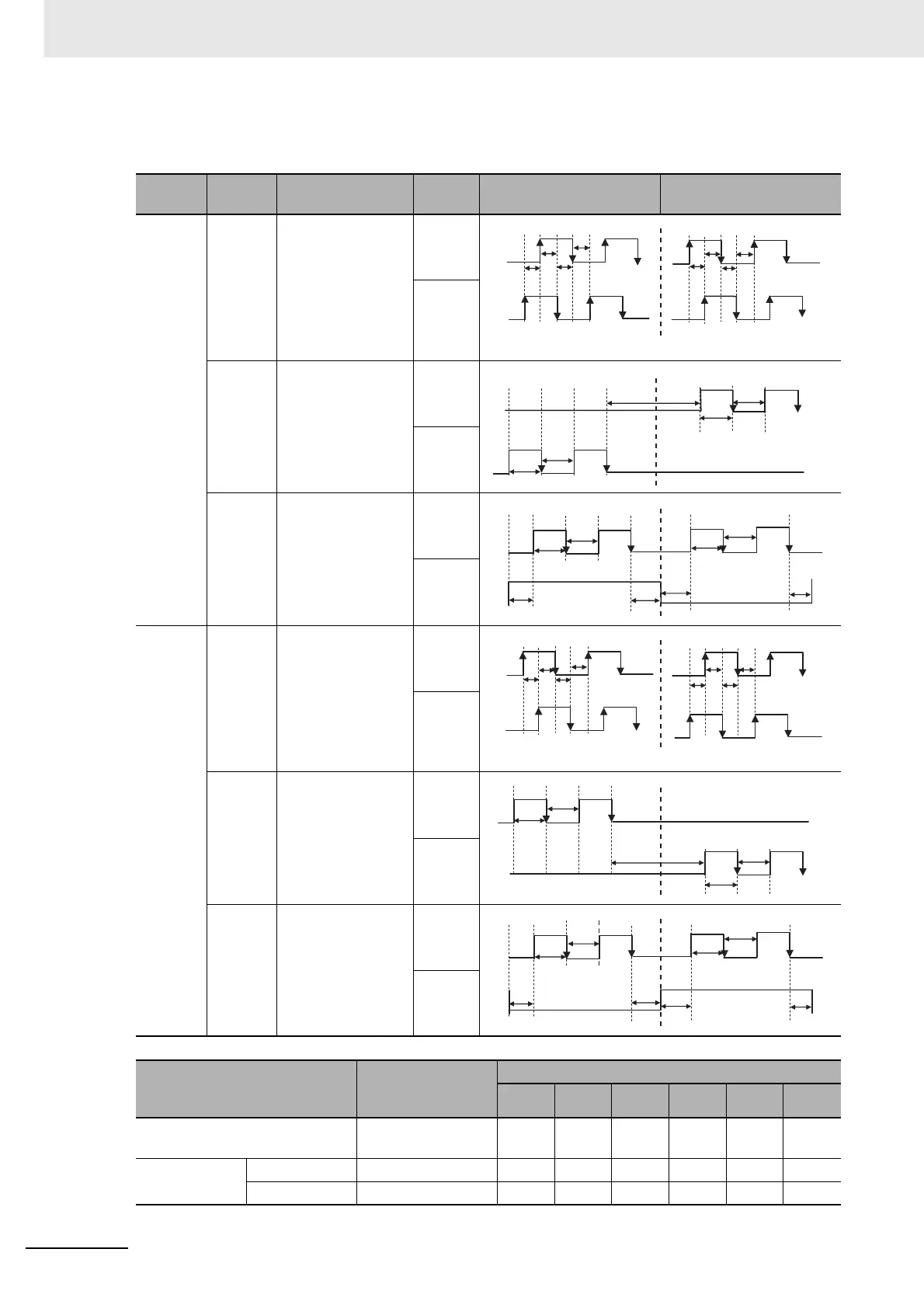
Command Pulse Rotation Direction Switching Selection and Command Pulse Mode Selection settings
are as follows.
Pn006 Pn007
Command pulse
pattern
Signal
Forward direction
command
Reverse direction
command
0 0 or 2 90° phase
difference
2-phase pulse
(Phase A and
Phase B)
PULS
SIGN
1 Forward direction
pulse train
+
Reverse direction
pulse train
PULS
SIGN
3 Pulse train
+
Sign
PULS
SIGN
1 0 or 2 90° phase
difference
2-phase pulse
(Phase A and
Phase B)
PULS
SIGN
1 Forward direction
pulse train
+
Reverse direction
pulse train
PULS
SIGN
3 Pulse train
+
Sign
PULS
SIGN
Symbol
Maximum
allowable input
frequency
Minimum required duration [µs]
t1 t2 t3 t4 t5 t6
+CWLD, –CWLD,
+CCWLD, –CCWLD
4 Mpps 0.25 0.125 0.125 0.125 0.125 0.125
+CW, –CW,
+CCW, –CCW
Line driver 500 kpps 2 1 1 1 1 1
Open collector 200 kpps 5 2.5 2.5 2.5 2.5 2.5
t1
t1
Phase
B
t1
t1
t1
Phase
A
t1
t1
t1
Phase B is 90° behind phase A.Phase B is 90° ahead of phase A.
t2
t2
t2
t2
t3
t4
t4
t5
t5
t6
L
H
t6
t6
t6
t1
t1t1
t1
t1
t1
t1
t1
Phase
B
Phase
A
Phase B is 90° behind phase A.
Phase B is 90° ahead of phase A.
t2
t2
t2
t2
t3
t4
t5
t4
t5
t6
t6
H
L
t6
t6
 Loading...


