7 Parameter Details
7 - 14
OMNUC G5-series (Pulse-train Input Type) AC Servomotors and Servo Drives User’s Manual
Explanation of Settings
(√: Enabled, –: Disabled)
• Select the conditions for switching between Gain 1 and Gain 2 when Gain Switching Input Operating
Mode Selection (Pn114) is set to 1.
• This setting is fixed to Gain 1 regardless of the gain input, when Switching Mode in Position Control
(Pn115) is set to 1 and Torque Limit Selection (Pn521) is set to 3 or 6.
*1 Gain Switching Delay Time in Position Control (Pn116) becomes effective when the gain is switched from 2 to 1.
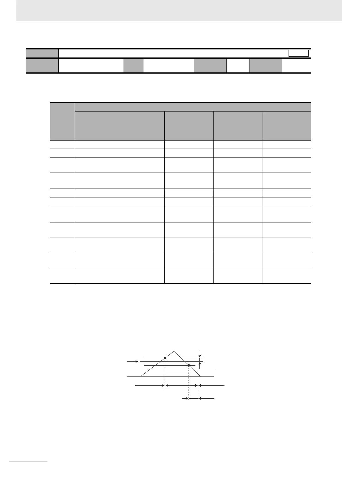
*2 The definition of Gain Switching Hysteresis in Position Control (Pn118) is shown in the drawing below.
*3 This represents the amount of change during the period of 1 ms.
Example: To switch the gain if the torque variation during 1 ms is 10%, set these parameters to 200.
*4 This represents the encoder resolution.
Pn115
Switching Mode in Position Control
Setting
range
0 to 10 Unit – Default
setting
0
Cycle the
power supply
–
Set
value
Description
Gain switching conditions
Gain Switching
Delay Time in
Position Control
(Pn116)
*1
Gain Switching
Level in Position
Control (Pn117)
Gain Switching
Hysteresis in
Position Control
(Pn118)
*2
0 Always Gain 1 (Pn100 to Pn104). – – –
1 Always Gain 2 (Pn105 to Pn109). – – –
2 Switching using gain switching input
(GSEL) for CN1 pin 27
–––
3 Amount of change in torque
command (Refer to Figure A.)
√
√
*3
(0.05%)
√
*3
(0.05%)
4 Always Gain 1 (Pn100 to Pn104). – – –
5 Command speed (Refer to Figure B.) √√ [r/min] √ [r/min]
6 Amount of position error (Refer to
Figure C.)
√
√
*4
[Pulse]
√
*4
[Pulse]
7 Command pulse input
(Refer to Figure D.)
√ ––
8 Positioning completion output (INP1)
OFF (Refer to Figure E.)
√ ––
9 Actual motor speed (Refer to Figure
B.)
√√ [r/min] √ [r/min]
10 Combination of command pulse input
and motor speed (Refer to Figure F.)
√
√
*5
[r/min]
√
*5
[r/min]
Position
Pn117
0
Pn118
Pn116
Gain 1
Gain 2
Gain 1

 Loading...


