2 Models and External Dimensions
2 - 48
OMNUC G5-series (Pulse-train Input Type) AC Servomotors and Servo Drives User’s Manual
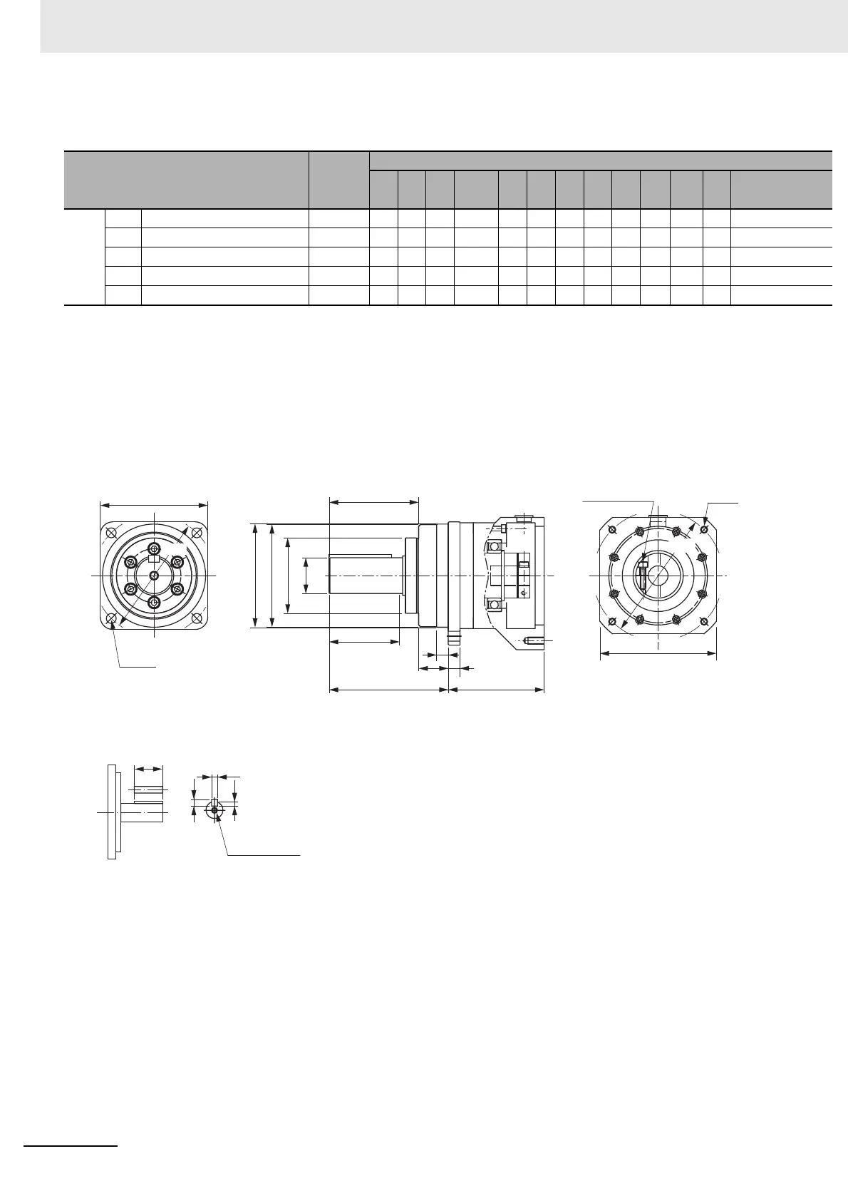
For 2,000-r/min Servomotors (1 kW)
Note 1 The standard shaft type is a straight shaft.
2 A model with a key and tap is indicated with J at the end of the model number (the suffix shown in the box). (Example:
R88G-HPG32A053K0BJ)
3 The diameter of the motor shaft insertion hole is the same as the shaft diameter of the corresponding Servomotor.
4 For Servomotors with a key, remove the key before use.
Outline drawing 1
Model
Outline
drawing
Dimensions [mm]
LM LR
C1 C2 D1 D2 D3 D4 D5 E F1 F2
1 kW 1/5 R88G-HPG32A053K0B 1
107 133 120
130
135 145 115 114 84 98 12.5
35
1/11 R88G-HPG32A112K0SB 1
107 133 120
130
135 145 115 114 84 98 12.5
35
1/21 R88G-HPG32A211K0SB 1
107 133 120
130
135 145 115 114 84 98 12.5
35
1/33 R88G-HPG50A332K0SB 2
123 156 170 ø
170
190 145 165 163 122 103 12
53
1/45 R88G-HPG50A451K0SB 2
123 156 170 ø
170
190 145 165 163 122 103 12
53
C1
4-φZ1
φSh7
φD5
φD4
φD3
E
T
F1
F2
LR
G
LM
C2
φD2
φD1
4-Z2
Set bolt (AT)
Key tap dimensions
QK
b
h
t1
M depth L

 Loading...


