Chapter 8: Maintenance
b.
Use a flat-blade screwdriver to unscrew and disconnect the Operator Panel's DB9
connecter (E).
3. Remove the top cover completely.
To replace the top cover:
1.
Pull out a short length of the antennae coaxial cables and the Operator Panel cable so
that they overhang the chassis.
2.
Lay the top cover at right angles across the chassis. Connect and tighten the cables to
prevent vibration from loosening them during normal AMR operation:
a.
Connect the coaxial cables (C) and (D) connected to both antennae and then
tighten with pliers.
b.
Connect the Operator Panel's DB9 connecter (E) and use a flat-blade screwdriver
to tighten the connector screws.
3.
Use the Torx driver to fasten all 14 M6 screws (A).
Release the E-Stop button to return the LD-250 to service. See: Releasing an E-Stop on page 31.
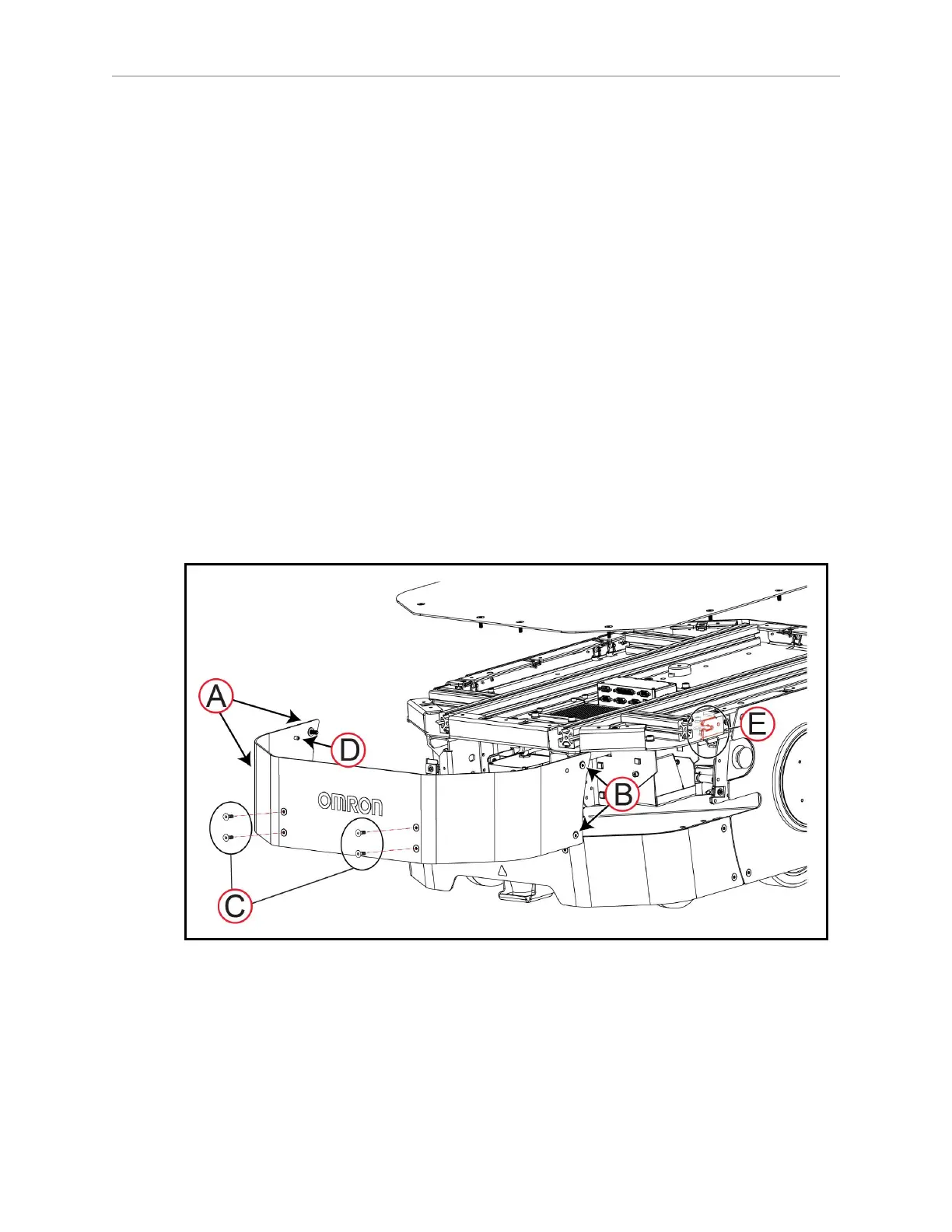
Remove and Replace the Upper Front Skin
The front upper skin covers the main safety and navigation laser. Take care that you do not
scratch the laser lens or damage the laser when removing the skin.
Figure 8-24 Remove the Upper Front Skin
Before you begin, press an E-Stop button to put the LD-250 into a safe state for maintenance
work.
To remove the upper front skin:
20472-000 Rev B LD-250 Platform User's Guide 181