: ON : OFF
Not
used
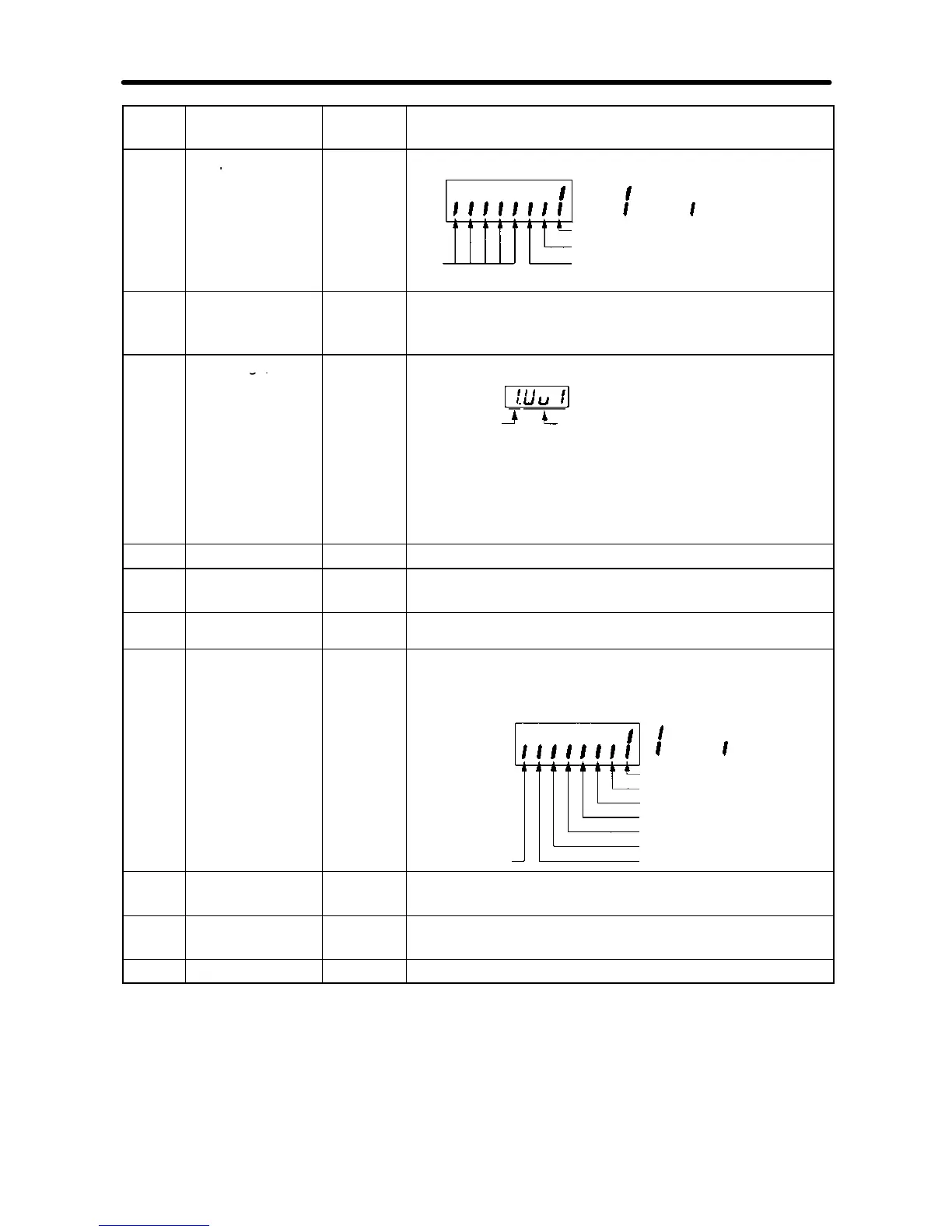
Terminal MA-MC: Multi-function contact output
Terminal P1-PC: Multi-function photo-coupler
output 1
Terminal P2-PC: Multi-function photo-coupler
output 2
U-08 Torque monitor % Displays the torque being currently output as a
percentage of the rated motor torque. This display
can only be made in vector control mode.
U-09 Error log (most
Error
Error
generation
item
Note “1” means that the latest error is displayed.
Press the Increment Key to display the second
latest error. A maximum of four errors can be
displayed.
U-10 Software No. --- OMRON use only.
U-11 Output power W Monitors the output power of the Inverter (see note
2).
U-13 Accumulated
operating time
x10H Monitor the accumulated operating time in 10-hour units.
(See note 3.)
U-15 Communications
error
--- Displays communications errors that occur during serial
communications (RS-422/RS-485). The errors that are
displayed have the same content as the serial
communications error at register number 003D Hex.
: Error
CRC error
: Normal
operation
Data length error
(Not used.)
Parity error
Overrun error
Communications time-over
(Not used.)
Framing error
U-16 PID feedback % Monitors the PID control feedback (Max. frequency:
100%)
U-17 PID input % Monitors the PID control input (Max. frequency:
100%)
U-18 PID output % Monitors the PID output (Max. frequency: 100%)
Preparing for Operation and Monitoring Chapter 3