67
Creating Ladder Programs Section 3-3
Press the OK Button twice to complete
writing output Q0. The highlighted cursor will
move to the input at the beginning of the next
line.
3-3-3-4 Writing a Parallel Input for Q0
Press the OK Button to display input I0 and
move the flashing cursor to the bit type I
position.
Press the Up Button to select Q (a CPU Unit
output bit).
Press the OK Button twice to complete
writing the parallel input for Q0. The
highlighted cursor will move to the next input.
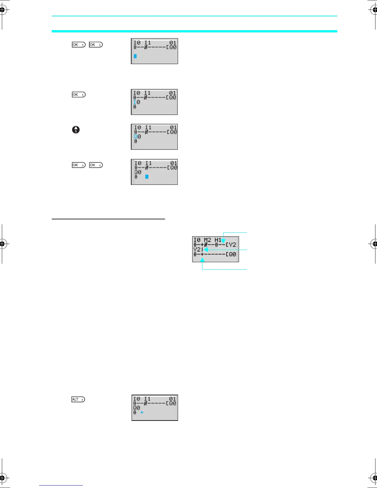
3-3-3-5 Drawing Connection Lines for OR Circuits
Drawing Connection Lines
Press the ALT Button when the highlighted
cursor is at the input write position to change
the cursor to a left flashing arrow and enable
connection lines to be drawn. Move the left
arrow the position for drawing the connection
line and press the Up, Down, Left, and
Right Buttons to draw connection lines
vertically and horizontally.
It will not be possible to draw connection
lines, if a written input/output bit has been
reached, if the beginning or end of the line
has been reached, or if the OK and ESC
Buttons are pressed.
Press the ALT Button to enable drawing
connection lines.
▼
▼
▼
▼
Horizontal connection lines
Vertical connection lines
Intersecting lines
▼
Z211-E1-03.book Page 67 Friday, November 21, 2008 10:38 AM