66
Creating Ladder Programs Section 3-3
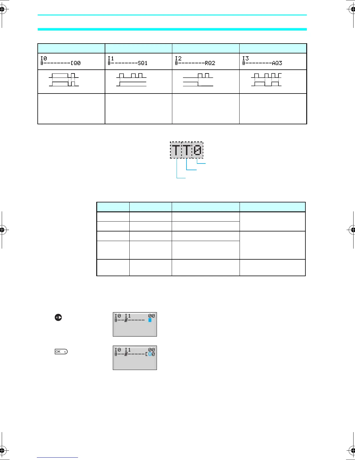
Additional Functions for Bit Outputs
Timers, Holding Timers, Counters, and Display Output Configurations
■ Timers, Counters, and Display Bits
Note
Cannot be used for LED-type CPU Units.
3-3-3-3 Writing an Output to Q0
Press the Right Button again to draw a line
to the output and move the highlighted cursor
to the output write position.
Press the OK Button to display the initial
value for the output (normal output/Q0) and
move the flashing cursor to the bit type Q
position.
Use the Up/Down Buttons to select the bit
type. Use the Right/Left Buttons to move the
flashing cursor and use the Up/Down
Buttons to select additional functions or
select the bit address.
[: Normal output S: Set R: Reset A: Alternate
Q0 turns ON and OFF
when execution
condition I0 turns ON
and OFF.
Q1 turns ON and stays
ON when execution
condition I1 turns ON
once.
Q2 is forced OFF
when execution
condition I2 turns ON.
Q3 alternates between
On and OFF each time
execution condition I3
turns ON.
I0
Q0
I1
Q1
I2
Q2
I3
Q3
Timer/counter/display number
Timer/counter/display type
Timer/counter output type
Symbol Name Type and number Output type
T Timer T0 to Tf (16 timers) T: Trigger
R: Reset
# Holding timer #0 to #7 (8 timers)
C Counter C0 to Cf (16 counters) C: Count
D: Count direction
R: Reset
F 8-Digit
counter
f0 (1 counter)
D Display bit D0 to Df (16 bits)
(See note.)
D
▼
▼
Z211-E1-03.book Page 66 Friday, November 21, 2008 10:38 AM