65
Creating Ladder Programs Section 3-3
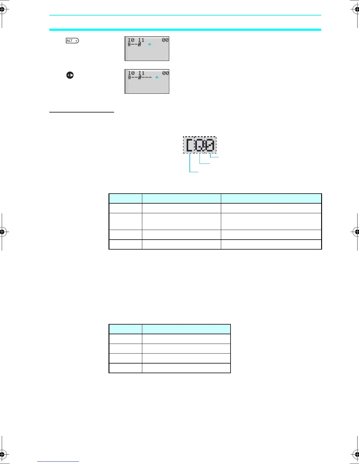
Press the ALT Button to enable drawing a
connection line. The left arrow cursor will
flash.
Press the Right Button to draw a connection
line to the output.
Writing Outputs
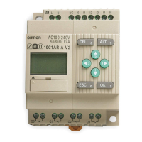
Output Configuration
■ Memory Areas
Note
1. Q0 to Q7 (8 points) for CPU Units with 20
I/O points. Q3 of CPU Units with
communications cannot be output
externally.
2. Can be used only when Expansion I/O
Units are connected.
■ Additional Functions for Output Bits
▼
▼
Bit number
Bit type
Additional functions
Symbol Name Bit type and number
Q CPU Unit output bits Q0 to Q3 (4 outputs) (See note 1.)
Y Expansion I/O Unit output
bits
Y0 to Yb (12 outputs) (See note 2.)
M Work bits M0 to Mf (16 bits)
H Holding bits H0 to Hf (16 bits)
Symbol Name
[ Normal operation
S Set operation
R Reset operation
A Alternate operation
Z211-E1-03.book Page 65 Friday, November 21, 2008 10:38 AM