64
Creating Ladder Programs Section 3-3
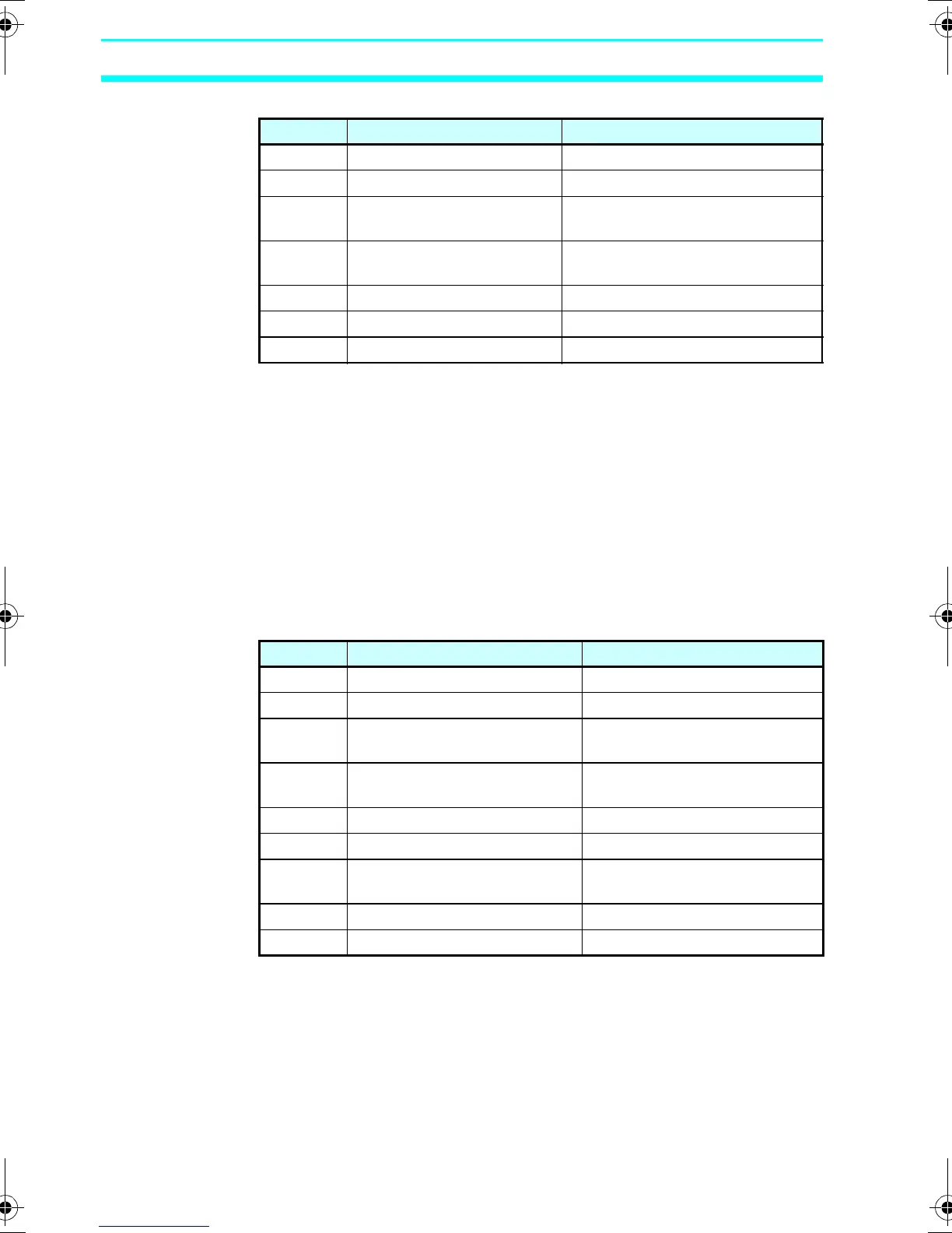
■ Memory Areas
Note
1. I0 to Ib (12 points) for CPU Units with 20
I/O points.
2. Q0 to Q7 (8 points) for CPU Units with 20
I/O points. Q3 of CPU Units with
communications cannot be output
externally.
3. Can be used only when Expansion I/O
Units are connected.
4. Cannot be used for LED-type CPU Units.
■ Timers, Counters, and Analog Comparators
Note 1. Can be used only when LCD-type CPU
Units are used.
2. Can be used only with CPU Units with
DC power supply (PNP connection).
Symbol Name Bit type and number
I CPU Unit input bits I0 to I5 (6 points) (See note 1.)
Q CPU Unit output bits Q0 to Q3 (4 points) (See note 2.)
X Expansion I/O Unit input
bits
X0 to Xb (12 points) (See note 3.)
Y Expansion I/O Unit output
bits
Y0 to Yb (12 points) (See note 3.)
M Work bits M0 to Mf (16 points)
H Holding bits H0 to Hf (16 points)
B Button switches B0 to B7 (8 points) (See note 4.)
Symbol Name Bit type and number
T Timers T0 to Tf (16 timers)
# Holding timers #0 to #7 (8 timers)
@ Weekly timers @0 to @f (16 timers) (See note
1.)
* Calendar timers *0 to *f (16 timers) (See note
1.)
C Counters C0 to Cf (16 counters)
F 8-Digit counter F0 (1 counter)
A Analog comparators A0 to A3 (4 comparators)
(See note 2.)
P Comparators P0 to Pf (16 comparators)
G 8-Digit comparators G0 to G3 (4 comparators)
Z211-E1-03.book Page 64 Friday, November 21, 2008 10:38 AM