VS 2001
Technical Handbook
Installation
Page 72 Marconi Proprietary information
P/N: 779-0373/02
Revision 02
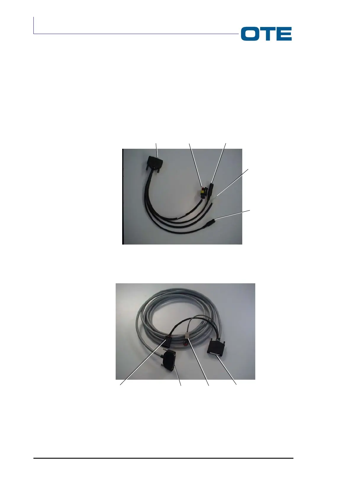
3.8 ELECTRICAL CONNECTIONS
In this chapter the cables for the VS 2001 equipment electrical connections are
described.
In Fig. 3.16 the multifunctional cable, to be connected to the Front Panel through
the DB15 connector (P04), is shown.
Fig. 3.16: Cabling between FPG1/A and accessories
Fig. 3.17: Cabling between FPG1/A and Radio Unit module
LOUDSPEAKER
To FPG1/A
MICROPHONE
PTT EXT
ALARM EXT
POWER
TO VS 2001
RADIO UNIT
To FPG1/A
AUX.
DEVICE