VS 2001
Technical Handbook
Accessories
P/N: 779-0373/02
Revision 02
Marconi Proprietary information
Page 69
Tab. 3.3: Pin functions of J2
Signal Pin Function Level
ALARM 4 INPUT FROM ALARM PUSH-BUTTON
0=ALARM
0 to +5 V
GND 5 GROUND 0 V
DATA FROM PC 3 FRONT PANEL SERIAL LINE (FROM
EQUIPMENT)
Standard RS232
DATA TO PC 2 FRONT PANEL SERIAL LINE
(TOWARDS EQUIPMENT)
Standard RS232
RTS FROM PC 7 FRONT PANEL SERIAL CONTROL Standard RS232
CTS TO PC 6 FRONT PANEL SERIAL CONTROL Standard RS232
PTT 1 PUSH TO TALK 0 to +5 V
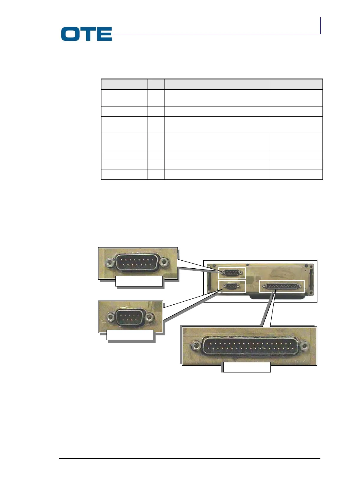
3.7.3.2
Rear side connectors
The FPG1/A rear connectors are shown in Fig. 3.15.
Fig. 3.15: FPG1/A rear side connector
The DB37 connector provides the interfacing of the FPG1/A to the Radio Unit
module.
The pin functions of the DB37 connector are listed in Tab. 3.4.
DB 37
DB 9
PEI
DB 15