VS 2001
Technical Handbook
Accessories
P/N: 779-0373/02
Revision 02
Marconi Proprietary information
Page 23
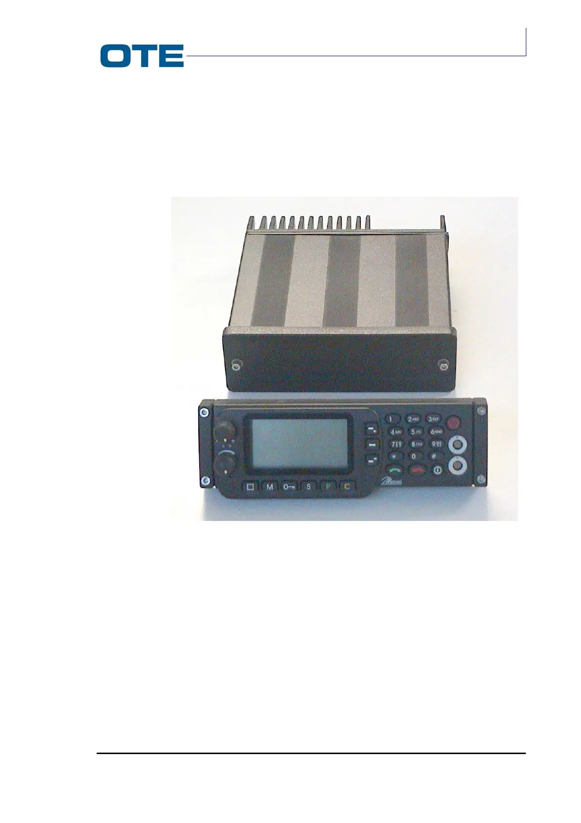
2.3 RADIO UNIT FUNCTIONAL DESCRIPTION
The Radio Unit module comprises a die-cast structure inserted in a metallic
container (tube) as shown in Fig. 2.2.
Fig. 2.2: Equipment structure: Radio Unit and Front Panel modules
The rear side of the Radio Unit container is made up of a finned surface to
dissipate heat (heat-sink). The internal space of the Radio Unit container is divided
into three compartments: a large one, on one side and two smaller on the other
side.
The Radio Unit electronic circuits are distributed on three cards:
• Base Band card (housed in the large compartment);
• R/T card (housed in the small front compartment);
• P.A. card (housed in the small rear compartment in direct contact with the
heat sink).