VS 2001
Technical Handbook
Technical Description
Page 26 Marconi Proprietary information
P/N: 779-0373/02
Revision 02
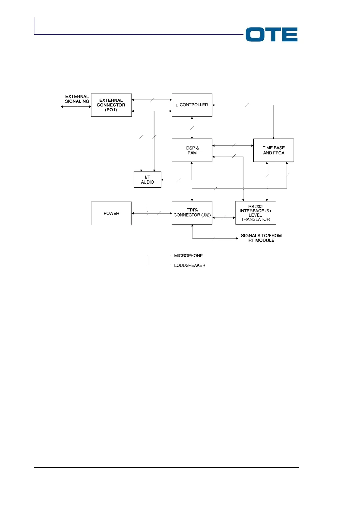
Fig. 2.6: Base Band functional block diagram
The Base Band card basically comprises the following functional blocks:
• I/F Audio;
• Microcontroller and Memories;
• DSP & RAM;
• Asic Time Base;
• RS232 interface & Level Translator circuit.
The card also contains:
• External connector;
• R/T and P.A. card interfacing connectors;
• Power Unit.