VS 2001
Technical Handbook
Installation
Page 68 Marconi Proprietary information
P/N: 779-0373/02
Revision 02
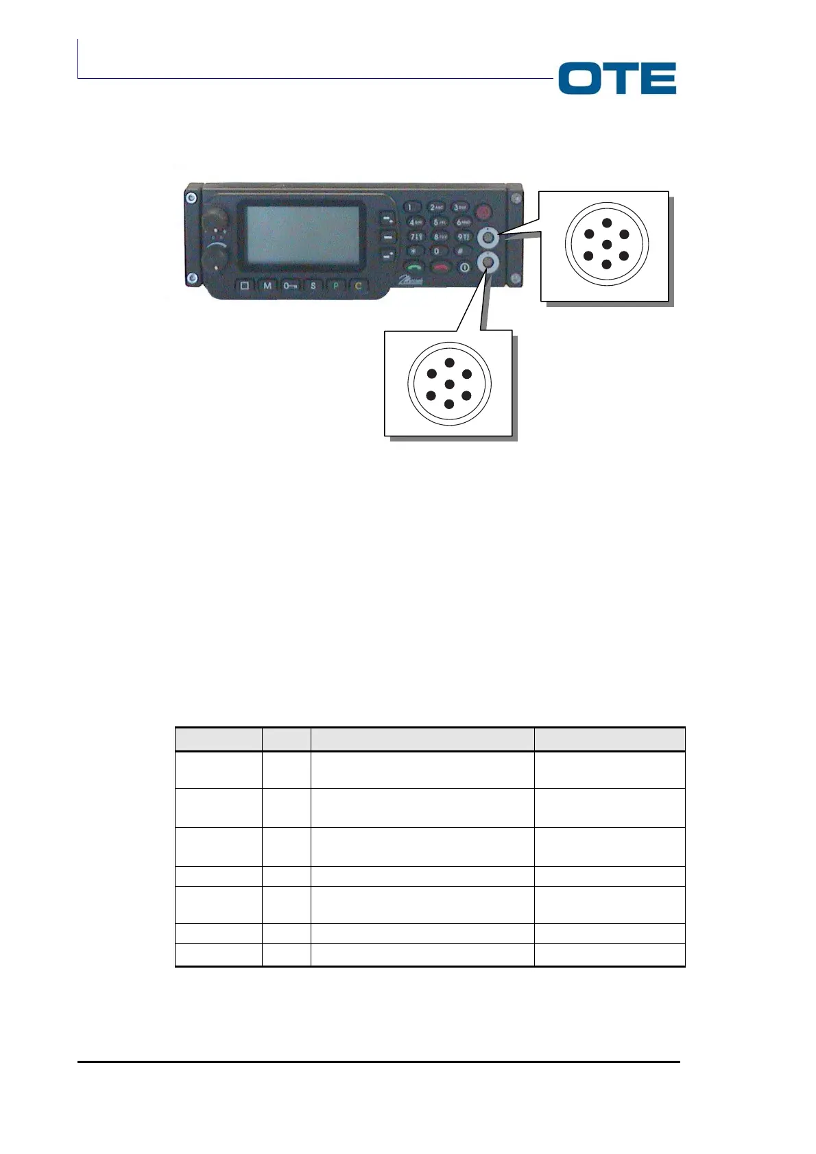
Fig. 3.14: FPG1/A front connectors
The J1 7-pin connector (see Fig. 3.14) provides the connection of a microphone or
an handset.
The J2 7-pin PEI connector (see Fig. 3.14) provides the connection of an external
PC.
The pin functions of J1 connector and of J2 connector are listed in Tab. 3.2 and
Tab. 3.3.
Tab. 3.2: Pin functions of J1
Signal Pin Function Level
MICRO
3 MICROPHONE INPUT 3.2 mV / Dynamic
microphone
HEADSET
CUFFIA
5 LF OUTPUT LOUDSPEAKER (FIRST
TERMINATION)
1.75 Vrms. / 300 Ω
PTT.MAN
4 PTT INPUT FROM OUTSIDE
0 = EQUIPMENT IN TX
0 to +BATT
RIT MICRO
2 MICROPHONE GROUND 0 V
+12
7 RELAY 12 (ACTIVATED BY HOOK) BATTERY VOLTAGE -
VOLTAGE DROPS
GND
1 GROUND 0V
HOOK
6 GENERAL PURPOSE INPUT 0 to +5 V
2
4
7
6
5
3
1
2
4
7
6
5
3
1
J1
J2