VS 2001
Technical Handbook
Accessories
P/N: 779-0373/02
Revision 02
Marconi Proprietary information
Page 39
2.3.2.2
R/T card interfacing
The interfacing between R/T and P.A. cards and between R/T and Base Band
cards is here described.
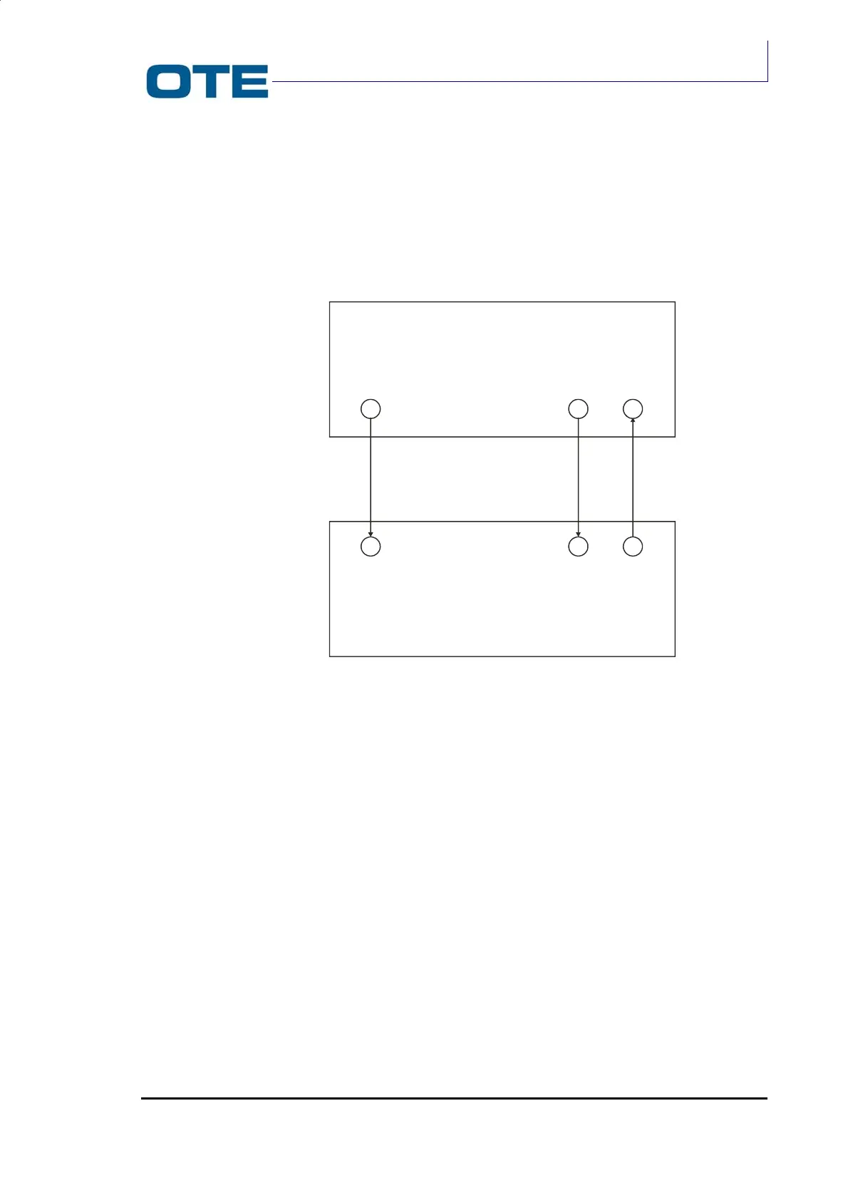
There are three connections between R/T and P.A. cards which are realised
through “MCX” type connectors. These connections are shown in Fig. 2.10.
Fig. 2.10: Connections between R/T and P.A. cards
The J11 connector is an output for the R/T card and is the Cartesian Loop direct
line. This connection terminates on the J14 connector of the P.A. card.
The J12 connector is an input to the R/T card and is the Cartesian Loop feedback.
This connection comes from the J16 connector of the P.A. card.
The J13 connector is the RX chain’s input and comes from the J15 connector of
the P.A. card.
The interfacing between R/T and Base Band cards is carried out through a 36-pin
connector. This connection takes place with dual strips which are inserted between
the two cards.
The cards’ connectors are both female.
The connection between R/T and Base Band cards is shown in Fig. 2.11.
P.A. CARD
R/T CARD
J15 J16
J14
J13
J12
J11