VS 2001
Technical Handbook
Technical Description
Page 28 Marconi Proprietary information
P/N: 779-0373/02
Revision 02
• Audio signal coming from microphone/handset;
• Audio signal to loudspeaker/headset;
• Power supply voltage provided by the vehicular battery;
• Control signals for external accessories.
The connection is carried out through the 25-pin male D-type connector (P01).
2.3.1.2
Base Band card interfacing
The physical interface between the Base Band card and the analogue part of the
vehicle equipment (R/T and P.A. cards) is carried out via two connectors:
• J02 (36-pin female connector) with relative filter capacitors. It constitutes the
interface with the low power analogue part (R/T card);
• J04 (6-pin female connector) with relative filter capacitors. It constitutes the
interface with the power transmission analogue part (P.A. card);
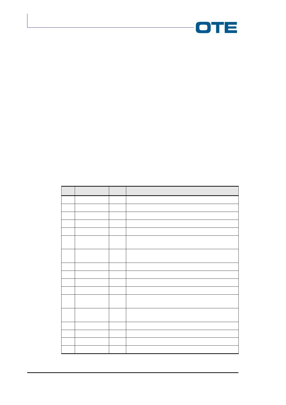
The allocation of the interface signals on these connectors and their meaning are
described in Tab. 2.1 and Tab. 2.2.
Tab. 2.1: J02 connector description
Pin Name Type Description
1 7.2 V PWR Analogue card power supply voltage
2 GND PWR Ground line
3 GND PWR Ground line
4 CK2304DA OUT Data synchronisation signal for Tx “air”
5 LATCH OUT Word synchronisation signal for Tx “air”
6 ITXD OUT Line for digital data relative to channel I of Tx for DAC
1866
7 QTXD OUT Line for digital data relative to channel Q of Tx for DAC
1866
8 SD OUT Shut down signal towards RT
9 TXON OUT O.C. control signal for transmission circuits on RT
10 PAON OUT O.C. control signal for transmission circuits on RT
11 SERDATAIN IN EEPROM reading serial line data on radio card
12 HCKSER OUT Clock synchronous serial line for 3 DAC quad, SINT and
EEPROM
13 HDATASER OUT Data synchronous serial line for 3 DAC quad, SYNTH
and EEPROM
14 HENDAC OUT Enabling signal for 3 DAC quad
15 HENEEPROM OUT Enabling signal for EEPROM present on RT card
16 HENSINT OUT Enabling signal for SINT present on RT card
17 GND PWR Ground line