VS 2001
Technical Handbook
Technical Description
Page 22 Marconi Proprietary information
P/N: 779-0373/02
Revision 02
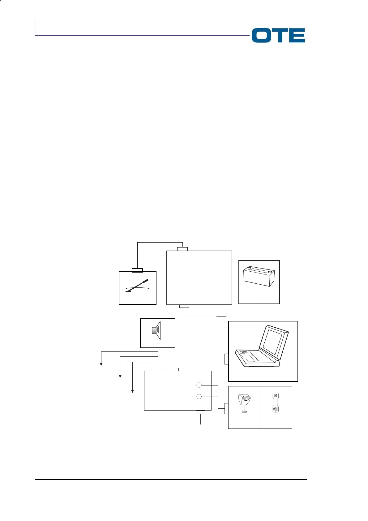
The DB15 connector provides the connection of a loudspeaker, an external
microphone, an external PTT and an external alarm.
The DB9 serial line PEI connector provides the connection of a PC for the
downloading of application software, setting-up of the operating parameters and
functional monitoring.
Both DB15 and DB9 connectors are placed on the rear side of the FPG1/A.
Radio Unit external connectors
There are two connectors on the rear side of the Radio Unit (heat sink side): a
BNC connector and a D type connector.
The J18 BNC connector provides the connection of the vehicular antenna.
The DB25 connector (P01) is a multifunction connector that includes:
• Power supply connector;
• Radio Unit / Front Panel connector;
• A main serial line (3-wire standard RS 232) to carry out a PEI connection with
a baud rate up to 115.2 kbit/s;
• An optional serial line (2-wire standard RS 232) with a baud rate up to 57.6
kbit/s.
Fig. 2.1: VS 2001 configuration scheme
VS 2001
RADIO UNIT
Car Battery
DB25
FUSE 16A (6-25 mm)
Antenna
Microphone
Handset
PC
JB
Loudspeaker
FPG1/A
J2 (PEI)
J1
MICROPHONE
EXT.
PTT
ALARM
EXT.
DB15
DB9 (PEI)
DB37