VS 2001
Technical Handbook
Technical Description
Page 46 Marconi Proprietary information
P/N: 779-0373/02
Revision 02
• The logic + display board, located on the internal side of the rear cover,
contains the circuitry for display control and interfacing;
• The interface board, located on the rear side of the Front Panel behind the
“Logic+display” board, hosts the connectors, which are available on the
control, panel rear cover.
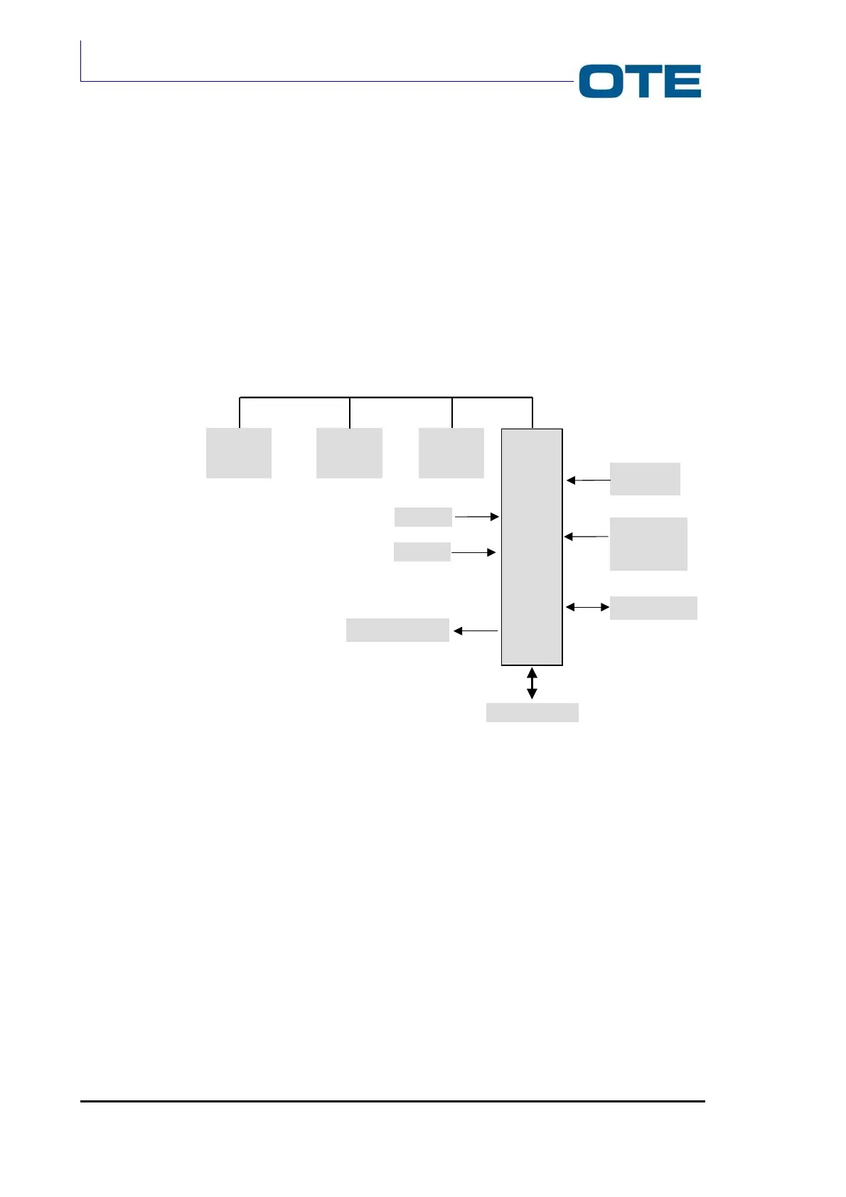
The architecture of the Front Panel logic board is shown in Fig. 2.16.
Fig. 2.16: Block diagram of the Front Panel
Ram Flash
Display
Module
µP
Radio Unit
interface
Groups
Volume
RS232
Red + green leds
Microphone /
Handset
interface
Keyboard