VS 2001
Technical Handbook
Technical Description
Page 50 Marconi Proprietary information
P/N: 779-0373/02
Revision 02
The kit (P/N 771-0955/01.01) contains 4 screws 3,5x25 (P/N 61510-56/001) for the
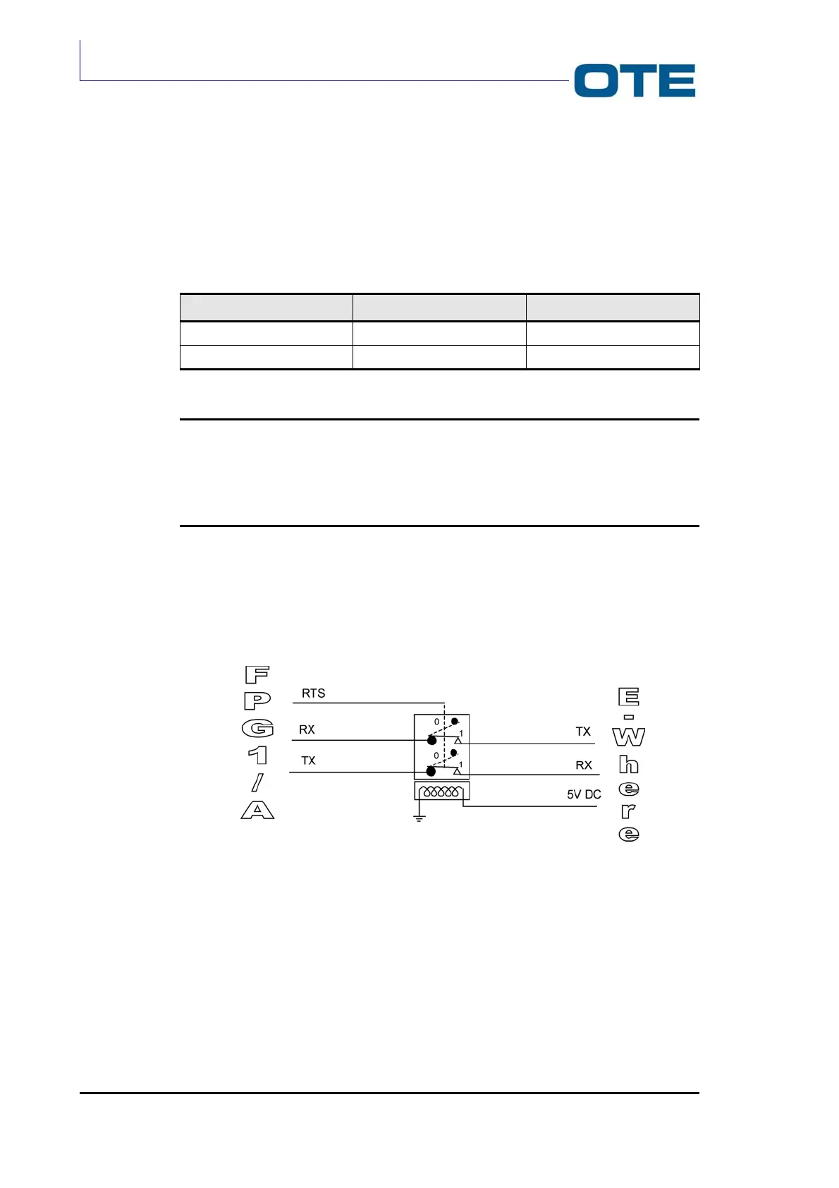
installation. The module is composed by a switch driven by RTS signal of PEI (pin
7 of FPG1/A serial line).
According to RTS signal logic levels, the switch is opened or closed for TX and RX
signals of RS232 towards E-WHERE module.
In details:
Logic Level RTS Electric Panel RTS Relé State
0 12 V Relé open
1 (default) -12 V Relé close
Note
The D9 serial connector (rear sides of remote control) is fisically in parallel with the data connector (front
side of remote control). When the kit is installed, by means management of the RTS signal it’s possible
to drive the switch. This connector is used for download the software towards the radio unit and the
remote control.
In Fig. 2.20 the equipment description is shown:
Fig. 2.20: Scheme of E-WHERE Module