VS 2001
Technical Handbook
Installation
Page 66 Marconi Proprietary information
P/N: 779-0373/02
Revision 02
3.7 EXTERNAL CONNECTORS
In this chapter all external connectors are described in detail and Pin function are
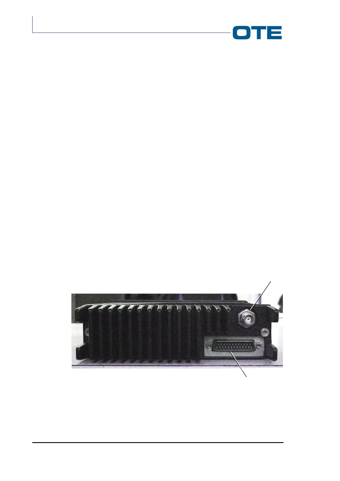
also explained. The Radio Unit module (see Fig. 3.13) hosts:
• Antenna connector (J18)
• Rear connector (P01)
On the FPG1/A Frontal Panel the following connectors are located:
• DB 37 (P02) connector;
• DB 15 (P04) connector;
• DB 9 (PEI) connector.
On the FPG1/A front side J1 and J2 connector are placed.
3.7.1 Antenna connector J18
It is a TNC female type connector located on the rear side (heat sink side) of the
Radio Unit module.
3.7.2 Main rear connector (P01)
The 25-pin male D-type connector located on the rear side of the Radio Unit
module is described in Tab. 3.1.
Fig. 3.13: Rear view
Antenna
connector
Rear connector (P01)