VS 2001
Technical Handbook
Accessories
P/N: 779-0373/02
Revision 02
Marconi Proprietary information
Page 29
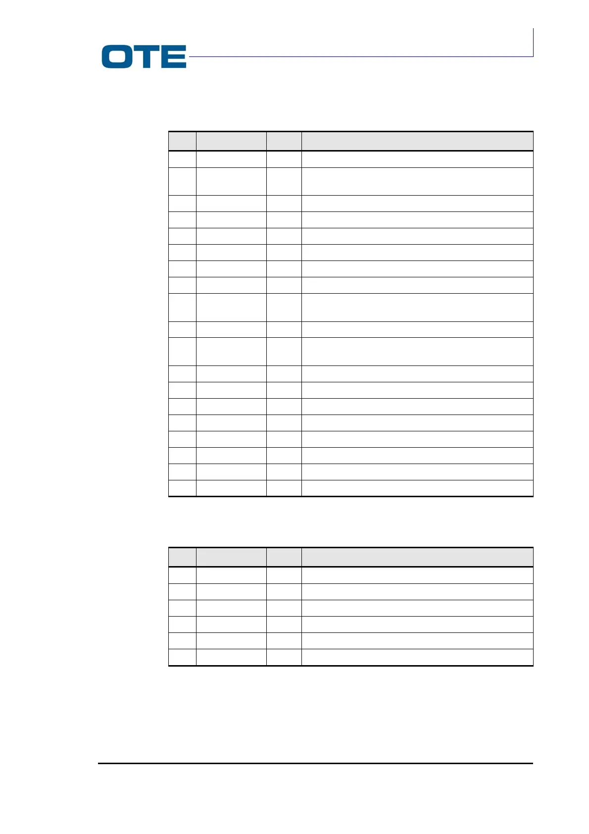
Tab. 2.1: J02 connector description (Cont’d)
Pin Name Type Description
18 GND PWR Ground line
19
Fref
IN
Reference frequency 12.8 MHz from R/T card to Base
Band
20 GND PWR Ground line
21 BSW OUT O.C. signal for setting operating frequency band
22 LD IN Signal for verification of correct operation of the SYNTH
23 GND PWR Ground line
24 HFRAMEAD OUT Frame synchronisation signal for control data AD7013
25 HDATAAD OUT Control data for AD7013
26 HCK2304AD IN Clock timing signal for data on synchronous control
serial line AD7013
27 HCK4608 OUT Master clock for AD7013
28 HFLAGIQ IN Frame timing signal for serial line data relative to
channels I and Q in reception
29 HIQRXAD IN Serial line relative to channels I and Q in reception
30 RXON OUT O.C. control signal for reception circuits on RT
31 GND PWR Ground line
32
GND
PWR
Ground line
33 GND PWR Ground line
34 GND PWR Ground line
35 GND PWR Ground line
36 7.2 V PWR Analogue card power supply voltage
Tab. 2.2: J04 connector description
Pin Name Type Description
1 VBATTINT PWR PA RF power supply voltage
2 VBATTINT PWR PA RF power supply voltage
3 GND PWR Ground line
4 GND PWR Ground line
5 VSWR IN VSWR signal
6 PAON OUT O.C. control signal for transmission circuits on PA RF